GROUND FAULT TESTING PROCEDURE
A ground fault test must be performed before installing the MotorSaver®Plus as required by
UL1053 and NEC, ANSI/NFPA 70.
1. Disconnect power.
2. Hook up the three line voltages to L1, L2, and L3 as required by the installation instructions.
3. Program the desired parameters into the unit. For test purposes, set MULT to 1 and GF to the
minimum allowed setting.
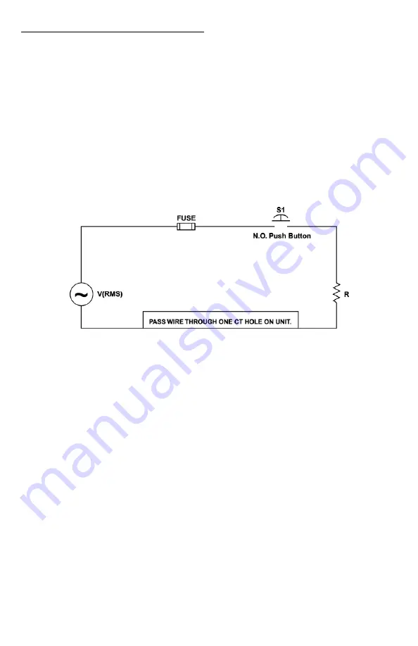
4. Construct the circuit, using an AC power supply. This circuit simulates a ground fault condition by
generating a current in one of the phases. Alternate test circuits may be used. The only
requirement is the current through the current transformer must be between 115% and 150% of
the GF setting and pass through only one CT window.
5. The values of V and R will be determined by the current required to generate a GF trip condition:
I = Vrms/R, where I = 115% of GF setting.
6. Place the unit in the RUN position, apply 3-phase power and allow the NO contact to close.
7. Energize the test circuit by pushing and holding the test pushbutton until the unit trips (within 8.5
seconds). The display should show “GrF” and the NO contacts should be open. Release the NO
pushbutton.
8. The results of the test are to be recorded on the test form provided below. The form should be
kept by those in charge of the building’s electrical installation in order to be available to the
authority having jurisdiction.
9. Confirm programmed parameters and proceed with installation instructions.
-
13 -
6/07 A1


