Chapter 1 Getting Started
Preparing the GPS Receiver for Use
1-10
Getting Started Guide
3
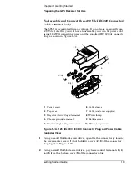
Slide the cable sleeve (
6
) over the cable (
7
).
4
Loosen the screw of
5
(
L
) terminal, and connect the positive (high)
voltage wire to the terminal.
The “L” terminal marking is inscribed inside the bottom cover (
9
).
5
Tighten screw. Soldering is not necessary.
6
Loosen the screw of
3
(
N
) terminal, and connect the negative (low)
voltage wire to the terminal.
The “N” terminal marking is inscribed inside the bottom cover (
9
).
7
Tighten screw. Soldering is not necessary.
8
Loosen the screw of
4
(
) terminal, and connect the ground (chassis)
wire to the terminal.
The “
” terminal marking is inscribed inside the bottom cover (
9
).
9
Tighten screw. Soldering is not necessary.
10
With the wires connected to the terminals (
3
,
4
, and
5
), re-insert the
terminal in their proper positions in the bottom cover (
9
)
.
11
Make sure that the cable sleeve’s (
6
) brim is placed in the groove or slot
in the bottom cover (
9
)
.
12
Clamp the wires down using the wire clamp (
8
). Position the clamp and
over the wires and attach and secure it to bottom cover (
9
) by
tightening the two screws (
10
).
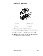
At this point, your connector plug and cable assembly should look
similar to Figure 1-2B.
Summary of Contents for 58503B
Page 13: ...1 Getting Started ...
Page 37: ...2 Features and Functions ...
Page 62: ...Chapter 2 Features and Functions In Case of a Problem 2 26 Getting Started Guide ...
Page 63: ...3 Using Option 001 Front Panel Display Keypad 58503B Only ...
Page 75: ...4 58503B Specifications ...
Page 80: ...Chapter 4 58503B Specifications Specifications and Characteristics 4 6 Getting Started Guide ...
Page 81: ...5 59551A Specifications ...
Page 86: ...Chapter 5 59551A Specifications Specifications and Characteristics 5 6 Getting Started Guide ...

