background image

Chapter 2  Features and Functions

Connecting a Computer or Modem

2-18

Getting Started Guide

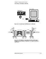
To Connect the 59551A to a Laptop Computer Via the 
Front-Panel PORT 2

Use the 9-pin (f) to miniature 9-pin (f) RS-232C interface cable 
supplied for a Laptop computer, and a “straight-through” type of 9-pin 
male-to-male adapter to connect the 59551A Module’s front-panel 

PORT 2

 DE-9S (female) connector to a laptop computer as shown in 

Figure 2-5.

Figure 2-5. Connecting the 59551A to a Laptop Computer 

OUTPUT

RS-232

59551A

GPS MEASUREMENTS SYNCHRONIZATION MODULE

Power

GPS Lock

Holdover

Alarm

59551A

Laptop Computer

Summary of Contents for 58503B

Page 1: ...3 12 Issue 1 Mar 00 Copyright 2000 Symmetricom Inc All rights reserved Printed in U S A 58503B GPS Time and Frequency Reference Receiver and 59551A GPS Measurements Synchronization Module Getting Started Guide ...

Page 2: ...sent to the Receiver via RS 232C port See the section Connecting to a Computer or Modem in Chapter 2 Features and Functions in this guide for instructions on connecting a computer or modem to these products For assistance contact Symmetricom Inc 2300 Orchard Parkway San Jose CA 95131 1017 U S A Call Center 888 367 7966 from inside U S A only toll free 408 428 7907 U K Call Center 44 7000 111666 Te...

Page 3: ...e 1 4 59551A Front Panel at a Glance 1 5 59551A Rear Panel at a Glance 1 6 Preparing the GPS Receiver for Use 1 7 Installation Precautions 1 7 Electrostatic Precautions 1 7 Electromagnetic Considerations 1 7 To Install the Antenna System 1 7 To Connect Power 1 8 To Connect AC Power 1 8 To Assemble and Connect the XLR DC Power Connector Cable Option AWQ for 58503B Only 1 8 To Assemble and Connect t...

Page 4: ... antenna cable 1 22 Set the Receiver s to exclude satellites which appear below a specified elevation angle 1 23 Set the Receiver s to display local time rather than UTC time 1 23 To Install With a Limited View of the Sky To Bypass Position Survey Operation 1 23 2 Features and Functions Chapter Contents 2 2 Inputs 2 4 Antenna Input 2 4 Recommended Antenna Cable Assemblies 2 4 Antenna Cable Length ...

Page 5: ...wn Cables 2 19 Configuring the RS 232C Port s 2 20 Making Changes to the Serial Port Settings If Needed 2 21 Configuring PORT 1 of the 59551A 2 21 Configuring PORT 1 of the 58503B and PORT 2 of the 59551A 2 21 Determining the Serial Port Settings 2 22 Standard 58503B and 59551A 2 22 Option 001 58503B 2 22 Operating Concepts 2 23 General 2 23 Holdover Description 2 23 In Case of a Problem 2 24 Hour...

Page 6: ...Access the TEST MODE to Test the Front Panel Display 3 5 To Access the DEMO MODE to Demonstrate Front Panel Capabilities 3 6 To Check Serial Port Settings During Installation 3 6 Error Messages 3 7 Status Messages 3 10 4 58503B Specifications Specifications and Characteristics 4 2 GPS Receiver Features 4 2 Other Information 4 5 Options and Accessories 4 5 5 59551A Specifications Specifications and...

Page 7: ...le commands to familiarize you with the GPS Receivers Chapter 2 Features and Functions provides information on GPS Receiver features and functions connecting to computers and problem solving that is a section titled In Case of a Problem Chapter 3 Using Option 001 Front Panel Display Keypad 58503B Only provides information on how to use the front panel display and keypad option Chapter 4 58503B Spe...

Page 8: ...following Input Output connectors an RS 232C serial communication port 25 pin female rectangular D subminiature on the rear panel a 1 PPS output BNC an optional 1 PP2S output BNC see page x and page 1 3 an Alarm output BNC 10 MHz output BNC an Antenna N type connector Power input jack The front panel contains four Light Emitting Diode LED indicators to indicate that power has been applied Power th...

Page 9: ...e time tagging inputs allow recording of time of occurrence of incoming edges timestamping for failure or sequence of events analysis The standard 59551A has the following Input Output connectors two RS 232C serial communication ports 9 pin female rectangular D subminiature on the front panel 25 pin female rectangular D subminiature on the rear panel an IRIG B output BNC a 1 PPS output BNC an Alar...

Page 10: ...672 Accessories Available GPS Accessories Refer to the subsections titled Recommended Antenna Cable Assemblies and Antenna Cable Length Delay in Chapter 2 of this guide for more cable information 58532A L1 Reference Antenna 58538A Lightning Arrestor 58539A Lightning Arrestor 58529A Antenna Line Amplifier with L1 Bandpass Filter recommended for distances greater than 53 3 meters for RG 213 cable 61...

Page 11: ...connectors attached 58520AA2 LMR 4001 Antenna Cable Assembly 1 to 110 meters without connectors attached 58521AA2 LMR 4001 Interconnect Cable Assembly 1 to 110 meters without connectors attached Serial Interface Accessories DTE to DTE 25 Pin m to 9 pin f RS 232 Interface Cable DTE to DTE 9 Pin f to 9 pin f RS 232 Interface Cable DTE to DCE 25 Pin m to f RS 232 Interface Cable 1 LMR 400 cables are ...

Page 12: ...e Manuals Supplied Manuals The following guides that document the 58503B and 59551A are shipped with the product 58503B 59551A Getting Started Guide this guide P N 097 58503 12 58503B 59551A Operating and Programming Guide P N 097 58503 13 ...

Page 13: ...1 Getting Started ...

Page 14: ... is receiving the GPS signal and is locked on one or more satellite s 3 When the Holdover indicator illuminates it indicates that the Receiver is NOT locked to the GPS signal The Receiver is keeping time based on the internal reference oscillator signal The internal reference oscillator will determine the accuracy of the 1 PPS signal and the 10 MHz reference output 4 When the Alarm indicator illum...

Page 15: ...s and has phase locked its internal reference to the reference provided by GPS When the Holdover indicator is illuminated it indicates that the Receiver is not phase locking its internal reference to the reference provided by GPS Typically this would happen due to loss of satellite tracking When the Alarm indicator is illuminated it indicates that the Module has detected a condition that requires ...

Page 16: ...er software 3 10 MHz OUT output for user specific applications 5 Option 002 1 PP2S One Pulse Per Two Seconds connector for outputting a pulse every other second synchronized to the even seconds in GPS time Pulses occur on even numbered seconds i e 2 seconds 4 seconds etc 6 Alarm output for external devices such as red light bell or horn to indicate that the Receiver has detected an internal condit...

Page 17: ...ne or more satellite s 4 When the Alarm indicator illuminates it indicates that the Module has detected an internal condition that requires attention 5 PORT 2 RS 232C DE 9S female serial interface port for local monitoring and retrieving data stored in the Module s memory data 3 When the Holdover indicator illuminates it indicates that the Module is NOT locked to the GPS signal The Module is keepi...

Page 18: ...ices such as red light bell or horn to indicate that the Module has detected an internal condition that requires attention The relay opens and closes with the Alarm indicator Mating connector is Amphenol part number 31 224 glass filled Noryl or 31 2226 Telfon 6 ANTENNA N type female connector for GPS antenna connection 4 Time tag input connectors for receiving TTL conditioned time tagging signals ...

Page 19: ... possible to define exact guidelines to assure electromagnetic compatibility If interference is suspected relocation of the GPS antenna usually solves the problem In worst case situations additional RF filtering may be required To Install the Antenna System CABLE CONSIDERATIONS When using the antenna cables with the GPS Receivers you should observe certain precautions Consult your local electrical...

Page 20: ...8503B Only 1 Note that you will have to assemble your own dc power cable using 18 AWG connecting wires and a three pin XLR female connector plug shown in Figure 1 1 Figure 1 1 Three Pin XLR Plug Pinouts Front View 2 From the rear of the XLR plug connect the supply side wire of the external power supply or battery to pin 1 of the XLR plug Connect the external battery s return ground wire to pin 2 a...

Page 21: ...igure 1 2A 129 Vdc IEC 300 DC Connector Plug and Power Cable Exploded View 1 Using a small flat blade screwdriver open the the connector by loosing the cover center screw 1 that holds two cover 2 9 of the connector plug together Figure 1 2A 2 Using a small flat blade screwdriver pry loose contact terminals 3 4 and 5 from the bottom cover 9 of the connector plug 1 Cover screw 6 Cable sleeve 2 Top c...

Page 22: ...en screw Soldering is not necessary 8 Loosen the screw of 4 terminal and connect the ground chassis wire to the terminal The terminal marking is inscribed inside the bottom cover 9 9 Tighten screw Soldering is not necessary 10 With the wires connected to the terminals 3 4 and 5 re insert the terminal in their proper positions in the bottom cover 9 11 Make sure that the cable sleeve s 6 brim is pla...

Page 23: ...covers 2 6 by properly positioning them together and tightening the wire clamp screws 4 14 Finally secure the two covers by tigthening the cover screw 1 15 Observing the correct polarity attach the other ends of the wires to a proper dc power source to operate the Module 1 Cover screw 4 Wire clamp screws 2 Top cover 5 Wire clamp 3 Cable sleeve 6 Bottom cover 1 2 6 5 4 3 4 ...

Page 24: ... shown in Figure 1 3 Figure 1 3 Connecting a PC or Terminal to the GPS Receiver You will need to run a terminal emulation program on your PC in order to communicate via the RS 232C serial port Most PCs contain a terminal emulation program especially PCs with Windows If your PC does not contain a terminal emulation program purchase one of the following programs PROCOMM PLUS DATASTORM Technologies I...

Page 25: ...select the appropriate port or connector COM1 or COM2 then click OK The COM1 or COM2 Properties dialog box is displayed This dialog box allows you to configure the RS 232 port of your PC 5 Set the RS 232 port of your PC to match the following default values Baud rate Bits per second 9600 Parity None Data bits 8 Stop bits 1 Pace flow control None NOTE The RS 232C port configurations of the GPS Rece...

Page 26: ...t Settings then choose Communications A dialog box is displayed that allows you to configure your PC 3 Set the RS 232 port of your PC to match the following default values Pace None Baud Rate 9600 Parity None Data Bits 8 Stop Bits 1 NOTE See the important NOTE on page 1 13 that provides information on what to do if the factory default values of the GPS Receiver s RS 232C port have been changed 4 I...

Page 27: ...east 8 minutes and at most 25 minutes to calculate its position from the constellation of satellites overhead The derived position will be improved over a period of time by further averaging When the GPS Lock indicator lights the basic functionality of the Receiver is available however optimal performance is delivered later To Power Up the Receiver 1 Connect the antenna system to the rear panel AN...

Page 28: ...r 5 Command Reference of the 58503B 59551A Operating and Programming Guide 58503 90013 for a complete description of the Alarm capability d The Receiver begins to search the sky for all available satellites e From the computer keyboard type SYSTEM STATUS and press Enter or Return If you typed in the command wrong a E xxx prompt is displayed after pressing Return Try typing in the command again The...

Page 29: ...status screen shown in Figure 1 4 This chapter of the operating and programming guide also provides a reference section that defines the different data indicated in the status screen SYNCHRONIZATION Receiver Status Outputs Valid ACQUISITION ELEV MASK Not Tracking 1 Locked to GPS UTC ANT DLY MODE AVG LAT AVG LON AVG HGT HEALTH MONITOR PRN Recovery Holdover Power up SmartClock Mode Tracking 6 Self T...

Page 30: ...ose Run b Type a setup and click OK or press Enter Return The SatStat Setup screen will appear and installation will proceed 3 Once the program is installed you can start it by double clicking the SatStat icon that was created during the installation 4 You should establish communication with the Receiver This requires connection from a serial RS 232 port on your PC to the GPS Receiver s PORT 1 por...

Page 31: ... query for the status of a setting of the Receiver use the Control Query form this form will usually be stacked beneath the main form To activate this form click anywhere on it Select Control or Query then choose the type of control or query you want This will pull down a list of control or query functions that you can choose from and the corresponding command will be displayed To send the command...

Page 32: ...ustomize the Receiver operation Execute a system preset if someone else has used the Receiver and left it in an unacceptable state Make the Receiver survey if it wasn t already surveying Set the antenna delay Set the elevation mask angle Set the time zone See the section titled Using Commands to Control Key Functions Examples on the following page for more information ...

Page 33: ...r connecting the Receiver to the antenna power source RS 232 port and after the self test is completed you may want to complete installation using one or more of the capabilities described below If required restore all of the Receiver s internal settings to their factory shipment values by invoking a system preset After executing the system preset the Receiver will begin normal operation it will a...

Page 34: ...verriding the survey operation and entering position data directly The survey is an iterative process The Receiver transits to Position Hold after it has suitably refined its position estimate Set the Receiver to survey using command GPS POSITION SURVEY ONCE Set the Receiver s to compensate for the length of the antenna cable The Receiver can be custom configured to compensate for the length of th...

Page 35: ...E TZONE hours minutes To Install With a Limited View of the Sky To Bypass Position Survey Operation In order to operate properly the Receiver must know its position The Receiver is able to collect enough information from four satellites to compute this position The position survey operation takes in data from the satellites iterating until the antenna position is known to the required precision Th...

Page 36: ...itude in degrees minutes seconds and altitude in meters above the GPS ellipsoid for the 58503B altitude in meters above mean sea level MSL for the 59551A Note if you know the position to this accuracy the desired position is of the antenna rather than the Receiver NOTE For faster acquisition following repair or power failure you may want to write down the position after the Receiver has completed ...

Page 37: ...2 Features and Functions ...

Page 38: ...ge 2 11 Alarm Output 58503B Only page 2 11 10 MHz OUT Output 58503B Only page 2 11 Indicators page 2 12 Power Indicator page 2 12 GPS Lock Indicator page 2 12 Holdover Indicator page 2 12 Alarm Indicator page 2 12 Serial Interface Ports page 2 13 PORT 1 Rear Panel RS 232C Serial Port page 2 13 PORT 2 Front Panel Serial Port 59551A Only page 2 14 Connecting to a Computer or Modem page 2 13 To Conne...

Page 39: ...Chapter 2 Features and Functions Chapter Contents Getting Started Guide 2 3 Operating Concepts page 2 23 General page 2 23 Holdover Description page 2 23 In Case of a Problem page 2 24 ...

Page 40: ...le Assemblies There are two types of cable assemblies recommended for connecting your antenna system LMR 400 or RG 213 Belden 8267 The following paragraphs describes when and how many line amplifiers are required with the LMR 400 and RG 213 cables LMR 400 Cable Line Amplifier Requirements If cable length between GPS Module and antenna is Less than 115 meters no line amplifier is necessary More tha...

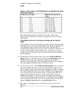
Page 41: ...ven these delay values per foot you can calculate the delay for your cable length Tables 2 1 and 2 2 list the delay values that you need to use with the GPS REFERENCE ADELAY seconds command for the available cable assemblies Table 2 1 Delay Values for the 58518A 519A and 58518AA 519AA RG 213 Antenna Cables The nominal delay value is labeled on the cables Refer to the Designing Your GPS Antenna Sys...

Page 42: ...o send the command to check this value After a moment the antenna delay value will appear on the Control Query form As shipped from the factory this value is 0 0 ns 2 To change this value select Control Antenna Delay on the Control Query form Enter the amount of delay desired For example to set 125 ns of delay enter 125 ns then select the enter key After a moment the response should be reply comma...

Page 43: ... a dc cable using the supplied IEC 320 dc connector plug part number 1252 5672 See Chapter 1 Getting Started for instructions Time Tagging Inputs 59551A Only The Time Tag 1 Time Tag 2 and Time Tag 3 BNC input connections allow you to input time tagging data to the Receiver using one of the following time tagging generators or equipment Sequence of Events Recorders Fault Analyzers Phasor Measuremen...

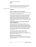
Page 44: ...holdover mode the timing 1 PPS accuracy will degrade as the holdover time increases 1 PP2S One Pulse Per Two Seconds Option 002 Output 58503B Only This optional output provides one pulse every other second synchronzed to the even seconds in GPS time This is the reference time used in CDMA base stations GPS even second pulses from the 1 PP2S option are used to synchronize the models 8921A options 6...

Page 45: ...e modulated code uses a 1 kHz carrier The sample IRIG B output shown in Figure 2 1 consists of time coded pulses that indicate the time as 173 days into the year 21 hours into the day 18 minutes into the hour and 42 seconds into the minute The sample IRIG B BCD output in Figure 2 1 also includes a Straight Binary portion which consists of time coded pulses that indicate the time of day as 76 722 s...

Page 46: ...FRAME 1 SECOND 2 ms BINARY 0 TYPICAL 5 ms BINARY 1 TYPICAL 01 SEC TYPICAL 1 2 4 8 10 20 1 2 4 8 10 20 4080 100 200 60 70 80 90 0 50 CONTROL FUNCTIONS TIME OF DAY STRAIGHT BINARY SECONDS 17 BITS P5 P7 P8 P9 P0 8 ms POSITION IDENTIFIER TYPICAL 01 SEC INDEX MARKER 1 SEC INDEX MARKER Time of this point equals 173 Days 21 Hrs 18 Mins 42 750 Sec X 3 3X TYPICAL MODULATED CARRIER Recommended Frequency 1 0...

Page 47: ...tact is open no alarm condition is indicated The relay opens and closes with the Alarm indicator Mating connector is Amphenol part number 31 224 glass filled Noryl or 31 2226 Telfon Alarm Output 58503B Only When an alarm condition exists the Alarm output is pulled down to a TTL low This signal may be used to drive an external visual e g red light or audio e g horn or bell device when the Receiver ...

Page 48: ...Manual Holdover When in holdover the outputs are still usable but the performance will be degraded from the locked state The longer the holdover condition persists the more degraded the outputs will become If the holdover has resulted from loss of GPS satellite tracking and tracking resumes the Receiver will automatically recover from holdover and become locked again NOTE If the Holdover indicator...

Page 49: ... page 2 15 and page 2 20 respectively Either port allows you full communication with the Receiver This can be done by connecting any computer with an RS 232C serial interface and suitable terminal emulation software then sending the correct commands for transmitting or retrieving data PORT 1 Rear Panel RS 232C Serial Port This 25 pin female subminiature D DB 25 connector PORT 1 RS 232C Serial Inte...

Page 50: ...2 5 NOTE We reserve the right to impose signals on other pins therefore your connection should be restricted to the pins described in Table 2 5 Refer to the section Connecting a Computer or Modem in this chapter on page 2 15 for wiring diagrams and more information on the RS 232C interface cables Table 2 5 PORT 2 Front Panel RS 232C Serial Port Connections 59551A Only Pin Number Input Output Descr...

Page 51: ...re also called null modem modem eliminator or crossover cables Most modems are DCE Digital Communication Equipment devices thus you must use a DTE to DCE interface cable The interface cable must also have the proper connector on each end and the internal wiring must be correct Connectors typically have 9 pins DE 9 connector or 25 pins DB 25 connector with a male or female pin configuration A male ...

Page 52: ...rface cable to connect the Receiver s rear panel PORT 1 DB 25 female connector to a PC or laptop as shown in Figure 2 2 Figure 2 2 Connecting the GPS Receiver to a PC or Laptop Connecting to a Modem Use an HP 40242M or equivalent interface cable to connect the Receiver s rear panel PORT 1 DB 25 female connector to a modem which is a DCE Digital Communication Equipment device as shown in Figure 2 3...

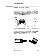
Page 53: ...r Combination for Laptop and PORT 2 Connection PC or Laptop GPS Receiver Rear view ANT 1 1 2 2 3 3 4 4 5 5 6 6 7 7 8 8 9 9 PC RS 232 9 pin RXD TXD GND DE 9P Male DE 9S Female PORT 2 RS 232 9 pin RXD TXD GND DE 9S Female DE 9S Female Interface Cable Instrument input Instrument output PC input PC output Data Terminal Equipment Data Communications Equipment 1 2 3 4 5 6 7 8 9 1 2 3 4 5 6 7 8 9 Adapter...

Page 54: ... RS 232C interface cable supplied for a Laptop computer and a straight through type of 9 pin male to male adapter to connect the 59551A Module s front panel PORT 2 DE 9S female connector to a laptop computer as shown in Figure 2 5 Figure 2 5 Connecting the 59551A to a Laptop Computer OUTPUT RS 232 59551A GPS MEASUREMENTS SYNCHRONIZATION MODULE Power GPS Lock Holdover Alarm 59551A Laptop Computer ...

Page 55: ...ace Connection to PORT 2 Figure 2 7 illustrates how to make a DE 9S to DB 25P DTE to DTE interface cable that can replace the 25 pin male to 9 pin female connectors for use with PORT 1 Figure 2 7 DE 9S to DB 25P DTE to DTE Serial Interface Connection to PORT 1 1 1 2 2 3 3 4 4 5 5 6 6 7 7 8 8 9 9 PC 232 9 pin RXD TXD GND DE 9P Male DE 9S Female PORT 2 RS 232 9 pin RXD TXD GND DE 9S Female DE 9S Fem...

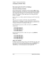
Page 56: ...le 2 7 list the configuration factory default values for PORT 1 and PORT 2 Procedures for configuring the RS 232C ports are provided in the following paragraphs Table 2 6 Factory Default Values for PORT 1 of the 59551A Parameter Default Possible Choices Software Pacing NONE XON or NONE Baud Rate 9600 1200 2400 9600 or 19200 Parity NONE EVEN ODD or NONE Data Bits 8 7 or 8 Stop Bits 1 1 or 2 Full Du...

Page 57: ...e the instrument will be updated but your computer will retain its original settings At each step you will have stopped serial communications and be forced to modify your PC settings to match the Receiver in order to continue It is recommended that you make all changes in a single compound command verify the changes and record all parameters Configuring PORT 1 of the 59551A Complete configuration ...

Page 58: ... full RS 232C communications enabling you to query the Receiver s communication settings Once you establish communications with one serial port you can query the Receiver for settings of either port Issue the following queries to either serial port to verify PORT 1 s configuration SYST COMM SER PACE SYST COMM SER BAUD SYST COMM SER PARITY SYST COMM SER BITS SYST COMM SER SBITS Issue the following ...

Page 59: ...pter 3 Visual User Interface of the 58503B 59551A Operating and Programming Guide Also using the appropriate SCPI query command will provide FFOM value refer to the operating and programming guide for specifics The GPS Receiver is designed to automatically detect and acquire satellites in order to begin providing precise frequency and time information Until such acquisition is complete and the ins...

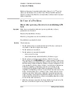
Page 60: ... too long cable with antenna attached neither shorted nor open Verify antenna is being properly driven Hint 1 Connect Tee connector to the ANTENNA input connect antenna cable to one end of Tee Measure a little less than 5 Volts from the other end of the Tee using a digital voltmeter DVM as shown in Figure 2 8 If your reading is a lot less than 5 Volts you will have to determine if the line amplifi...

Page 61: ...mand Symptom Position data correct Sufficient satellites in view No satellites tracked Solution If candidate satellites are marked Ignore on status screen disable the feature which ignores satellites If candidate satellites are below the mask angle specified on the Receiver Status screen lower the elevation mask angle using the proper command Default is 10 degrees all satellites between the horizo...

Page 62: ...Chapter 2 Features and Functions In Case of a Problem 2 26 Getting Started Guide ...

Page 63: ...3 Using Option 001 Front Panel Display Keypad 58503B Only ...

Page 64: ...t Compatibility page 3 3 System Compatibility page 3 3 Using the Display and Keypad page 3 4 To Display Time page 3 4 To Display Position page 3 4 To Display Number of Satellites Being Tracked page 3 4 To Display Serial Port Settings page 3 5 To Display System Status page 3 5 To Clear Instrument Alarm page 3 5 Capabilities Under Special Circumstances page 3 5 To Access the TEST MODE to Test the Fr...

Page 65: ...n 001 Front Panel Display Keypad is available as an option for the 58503B GPS Time and Frequency Reference Receiver System Compatibility Information displayed on the front panel corresponds with the same information available by other means Two instruments which are synchronized and racked side by side will increment in unison Similarly the instrument display will increment in unison with the SatS...

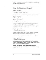
Page 66: ...progresses The longitude is displayed in the format E or W longitude degree longitude minute and longitude second Displaying Latitude Press Lat key to display latitude Following power up the Receiver iteratively computes its position the latitude display is updated as computation progresses The latitude is displayed in the format N or S latitude degree latitude minute and latitude second Displayin...

Page 67: ...s Under Special Circumstances To Access the TEST MODE to Test the Front Panel Display Access the product s installation TEST MODE using the following procedure 1 Apply power to the 558503B While the letters HP are moving from right to left about 2 seconds press the Sat key followed by the Time key If necessary you can remove and re connect power to re initiate the startup and try again When you su...

Page 68: ... try again When you succeed the product will enter its DEMO MODE The DEMO MODE does not require an antenna connection DEMO MODE was designed to support the user during demonstrations during installation and during initial connection to a PC The DEMO MODE responds to keypresses by displaying simulated data for UTC Time Longitude Latitude Altitude Satellite Count and Status These values are not rela...

Page 69: ...be configured to detect onset of conditions and or abatement of conditions The display identifies which has occurred For example the status system can be configured to detect the onset of holdover exit from holdover or both onset and exit The display distinguishes these events by appending a minus sign if the abatement of the condition is detected if a negative transition is detected It presents a...

Page 70: ...eds tolerance Hardware 2 POS 5V ER 5 volt supply voltage exceeds tolerance Hardware 3 OVEN TOLER Oven supply exceeds tolerance Hardware 4 EFC NR LMT EFC oscillator electronic frequency control voltage near full scale Hardware 6 EFC LIMIT EFC voltage at full scale Hardware 7 GPS PPS ER Invalid GPS engine 1 PPS signal Hardware 8 GPS FAILED GPS engine not communicating Hardware 9 TI MEAS ER Measureme...

Page 71: ...mmary bit Status Byte 3 CMD ER SUM Command Err register summary bit Status Byte 5 MSTR SUM Master summary bit Status Byte 6 OPER SUM Operation register summary bit Status Byte 7 When the Alarm LED is illuminated by an error condition the instrument display will show the cause of the alarm Until the alarm is cleared the displayed alarm error message will have priority over any other message on the ...

Page 72: ...uted Altitude key pressed data not yet valid UTC numerics During normal operation on keypress Current UTC time uncorrected for local time zone offset LOCAL numerics During normal operation on keypress Current UTC time corrected for local time zone offset LAT numerics During normal operation on keypress Latitude LONG numerics During normal operation on keypress Longitude ALT numerics During normal ...

Page 73: ...ation is specified numeric Note if numeric exceeds 99 59 the label MAX appears numeric HLD LIM Holdover Holdover initiated when time error between internal and external 1 PPS signals exceeded limit Holdover duration is specified numeric Note if numeric exceeds 99 59 the label MAX appears numeric HLD GPS Holdover Holdover initiated on loss of GPS satellites Holdover duration is specified numeric No...

Page 74: ...Chapter 3 Using Option 001 Front Panel Display Keypad 58503B Only Status Messages 3 12 Getting Started Guide ...

Page 75: ...4 58503B Specifications ...

Page 76: ...de Specifications and Characteristics The specifications and characteristics of the 58503B GPS Time and Frequency Reference Receiver are provided in this chapter GPS Receiver Features Eight channel parallel tracking GPS engine C A Code L1 Carrier SmartClock technology Enhanced GPS technology ...

Page 77: ...utes of operation It has a 95 probability of meeting unlocked holdover specifications after 24 hours of warmup followed by GPS locked for 48 hours The longer GPS Receiver and its quartz oscillator operates the better its stability and unlocked holdover performance becomes 1 PPS Output Specifications Locked Jitter of leading edge 750 ps rms with at least one satellite in view SA on Time Accuracy 11...

Page 78: ...8 to 264 Vac automatically selected 50 to 60 Hz Option AWQ Unit accepts 24 Vdc or 48 Vdc nominal Actual operating range 19 to 60 Vdc operating range Greater than 23 Vdc required to start Input Power all options 35 watts nominal Weight and Size Dimensions 88 5 mm H 212 6 mm W 348 3 mm D Half Rack Module Weight 3 6 kg 8 lbs 10 MHz Root Allan Variance ...

Page 79: ... azimuth SmartClock State locked holdover etc antenna coordinates time and frequency figures of merit and other data In addition a clock window is provided to display time of day in real time Finally SatStat allows you to easily change many receiver parameters such as antenna delay by simply picking the item from a pop up menu and entering a new value With SatStat and a PC you can monitor and cont...

Page 80: ...Chapter 4 58503B Specifications Specifications and Characteristics 4 6 Getting Started Guide ...

Page 81: ...5 59551A Specifications ...

Page 82: ...ide Specifications and Characteristics The specifications and characteristics of the 59551A GPS Measurements Synchronization Module are provided in this chapter GPS Receiver Features Eight channel parallel tracking GPS engine C A Code L1 Carrier SmartClock technology Enhanced GPS technology ...

Page 83: ...ced the oscillator may take up to one week to reach its specified aging rate and to operate without significant frequency jumps When a GPS Receiver is initially turned on and locked to the GPS satellite system it will achieve GPS lock within 30 minutes of operation It has a 95 probability of meeting unlocked holdover specifications after 24 hours of warmup followed by GPS locked for 48 hours The l...

Page 84: ... 80 C Antenna 58532A Operating 40 C to 80 C Storage 40 C to 85 C Power Requirements AC Power 90 to 132 Vac or 198 to 264 Vac automatically selected 50 to 60 Hz or DC Power 129 Vdc nominal 115 to 140 Vdc operating range Input Power all options 35 watts nominal Weight and Size Dimensions 88 5 mm H 212 6 mm W 348 3 mm D Half Rack Module Weight 3 6 kg 8 lbs Surge Withstand Meets IEEE ANSI C37 90 C37 9...

Page 85: ... azimuth SmartClock State locked holdover etc antenna coordinates time and frequency figures of merit and other data In addition a clock window is provided to display time of day in real time Finally SatStat allows you to easily change many receiver parameters such as antenna delay by simply picking the item from a pop up menu and entering a new value With SatStat and a PC you can monitor and cont...

Page 86: ...Chapter 5 59551A Specifications Specifications and Characteristics 5 6 Getting Started Guide ...

Page 87: ...tenna x xi LMR 400 2 4 recommended 2 4 RG 213 1 7 RG213 2 4 cable assemblies 2 4 cable length delay 2 5 cables 2 5 crossover 2 15 HP 58521AA xi HP 24542G interface 2 16 HP 24542U 2 19 HP 40242M interface 2 16 HP 58518A x HP 58518AA xi HP 58519A x HP 58519AA xi HP 58520A xi HP 58520AA xi HP 58521A xi modem eliminator 2 15 null modem 2 15 CDMA base stations 2 8 characteristics 58503B 4 2 59551A 5 2 ...

Page 88: ...t 1 24 help from HP 1 7 2 4 2 5 Holdover 1 2 holdover 2 12 holdover description 2 23 Holdover indicator 2 12 Holdover LED 1 3 1 5 holdover mode viii ix 1 2 1 5 HP 58503B Receiver viii HP 58518A cable x HP 58518A 519A cable 2 5 HP 58518AA cable xi HP 58518AA 519AA cable 2 5 HP 58519A cable x HP 58519AA cable xi HP 58520A cable xi HP 58520A 521A cable 2 6 HP 58520AA cable xi HP 58520AA 521AA cable 2...

Page 89: ...y Keypad 3 1 3 3 Option 002 1 PP2S Output x Option 002 1 PPS2 2 8 Option 1CM Rack Mount x Option AWR Power Supply x Option AXB Rack Mount x options x output 1 PPS 1 4 1 6 2 8 10 MHz 2 11 10 MHz OUT 1 4 Alarm 1 4 2 11 Alarm BITE 1 6 2 11 IRIG B 1 6 2 8 Programmable Pulse 1 6 programmable pulse 2 8 outputs 2 8 1 PP2S optional 1 4 2 8 1 PPS 1 6 IRIG B 1 6 Programmable Pulse 1 6 P pace 2 20 parity 2 2...

Page 90: ...port configuring 1 13 1 14 setting 1 13 1 14 serial port settings 2 22 settings serial port 2 22 software pacing 2 20 specifications 58503B 4 2 59551A 5 2 status display 3 5 status messages 3 10 status reference documentation 3 7 Status Screen 1 17 status screen 1 18 steady state operation 1 15 stop bits 2 20 survey using command 1 22 surveying 1 22 SYSTEM PRESET command 1 21 STATUS 1 16 STATUS co...

Reviews: