6000-100Ch1.fm Rev. D
TimeVault™ User’s Manual
1-7
Front Panel Interface
Chapter 1: General Information
1.12
Front Panel Interface
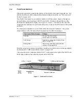
This section provides a general description of TimeVault’s front panel input devices. For
details about how to enter commands and interpret display readouts, see “Overview and
Format” on page 4-49.
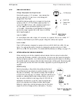
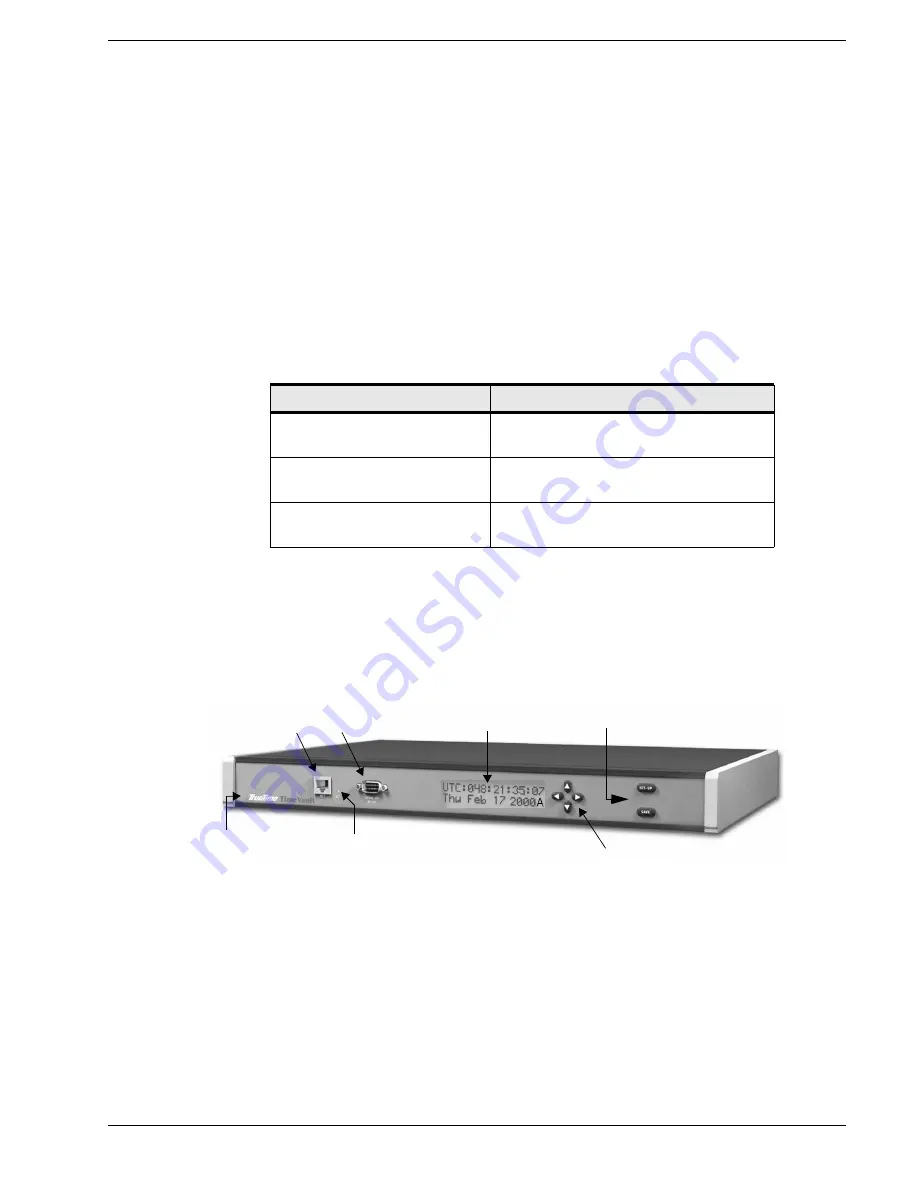
TimeVault’s front panel is your primary interface with the system. Input is through six
keypad buttons (four directional,
SET-UP
and
SAVE
). Output is through the two-line,
20-character alphanumeric display (see Figure 1-1, below). The letter at the end of the
output date line indicates the synchronization source in use (
G
for GPS,
A
for ACTS and
N
for NTP).
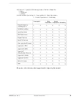
Two front panel mounted, tri-color LEDs reflect the status of TimeVault. The system
status indicator at the left end of the front panel has five different displays:
Possible causes and solutions for problems resulting in a solid red or solid orange display
are discussed in “LED System Status Alerts” on page 5-89.
The connection active indicator, labeled “ACT” and located to the right of the NET Port’s
RJ-45 plug, indicates the connection speed on the NET Port.
Figure 1-1 TimeVault Front Panel
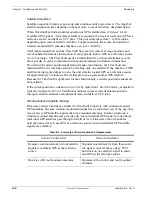
If the System Status Displays...
It Means...
Solid Red
No signal from time sources,
or major alarm fault detected
Solid Orange
TimeVault is synchronized to Network Time
Servers through NTP
Blinking Green
The primary or secondary synchronization
source(s) is fully operational
Alphanumeric
Display
SET-UP and SAVE Push-Button
NET Port Serial I/O
Directional Push-Buttons
System
Status
Indicator
Connection Active
(“ACT”)
Indicator
Summary of Contents for Time Server
Page 1: ...6000 100 Revision D January 2 2003 TimeVault Trusted Time Server User s Manual TM ...
Page 7: ...6000 100Front fm Rev D TimeVault User s Manual v ...
Page 10: ...viii TimeVault User s Manual 6000 100Front fm Rev D ...
Page 24: ......
Page 118: ......
Page 138: ......
Page 142: ......
Page 148: ......


