background image

098-00172-000 Revision A – December, 2009

TimeProvider 500 2.0 User’s Guide

19

How to Use This Guide

User’s Guide Updates

Manual updates are available by logging in to Telecom Solutions Support at: 

http://www.symmetricom.com/support/online-support//

Note:

 If you are downloading a manual for the first time, you will need 

to register with Symmetricom. If you are currently registered, login 
and download the manual update.

Summary of Contents for TimeProvider 500

Page 1: ...TimeProvider 500 IEEE 1588v2 Translator 2 0 User s Guide Revision A December 2009 Part Number 098 00172 000 ...

Page 2: ...CA 95131 1017 U S A http www symmetricom com Copyright 2009 Symmetricom Inc All rights reserved Printed in U S A All product names service marks trademarks and registered trademarks used in this document are the property of their respective owners ...

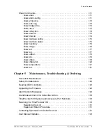
Page 3: ...er s Guide Updates 18 Chapter 1 Overview Overview 21 Key Features 22 Hardware Features 22 Software Features 22 Telecommunications Using PTP 23 Version 2 0 Features 24 Hardware 24 Software 24 Functional Overview 25 Functional Description 26 PowerA and PowerB Connectors 26 RJ48C Connectors 27 1PPS E1 T1 Output Connectors 27 10MHz Connector 29 LEDs 29 Chassis Ground 30 RS232 MGMT Serial Port 30 IEEE ...

Page 4: ...gure VLAN Settings Example 49 Installation and Provisioning Checklist 50 Chapter 3 Operations Introduction 53 PTP Management 54 Interface Connections 55 PTP Devices 55 Remote CLI Command Access 55 All interface connections are available for VLAN and non VLAN remote telnet sessions 55 Interface Connection Considerations 55 if0 if1 if2 if3 if4 56 Reviewing Interface Configurations 58 Multicast Suppo...

Page 5: ...clear log 81 help 81 logout 82 ping 82 reboot system 83 upgrade 83 Set Commands 84 set auto neg 85 set bridge time 85 set clock time 86 set clock timescale 86 set clock timezone 87 set configuration 88 set eia 232 baud 88 set firewall 88 set interface 89 set interface attachments 89 set ip 91 set ipdv interval 92 set ipdv pacing 92 set ipdv reset 93 set ipdv threshold 93 set ip mode 94 set tod 94 ...

Page 6: ...Output Commands 101 set output freerun 101 set output hdb3 102 set output holdover 102 set output out1 out2 out3 out4 103 set output pps mode 104 set output pps offset 104 set output pps width 105 Set PTP Commands 106 set ptp addr mode 106 set ptp address 106 set ptp domain 107 set ptp dscp 108 set ptp mgmt 108 set ptp transport 109 set ptp unicast announce int 109 set ptp unicast lease int 110 se...

Page 7: ... show led 117 show log 117 show output 118 show ptp 118 show status 119 show status list 120 show temperature 121 show tod 121 Chapter 5 Maintenance Troubleshooting Ordering Preventive Maintenance 123 Safety Considerations 124 Reading LED Conditions 125 Upgrading the Firmware 126 Alarm System Messages 126 Grandmaster Clock Link Corrective Action 130 TimeProvider 500 System and Accessory Part Numbe...

Page 8: ... 138 Holdover 138 Typical Performance 139 Factory Defaults 140 Electromagnetic Environment 141 Regulatory Requirements 142 Appendix A Tmecode Formats NMEA Format 143 T1 Format 144 Appendix B Configuring the TimeProvider 5000 and 500 Exam ple TimeProvider 5000 and 500 Configuration Example 147 Appendix C Hardware Version 1 0 Units Version 1 0 Component Functional Description 154 Power Connector 154...

Page 9: ...ironmental 159 Power 159 Serial Port 160 Ethernet Port 160 T1 Outputs 161 1 544 MHz Outputs 161 E1 Outputs 161 2 048 MHz Outputs 162 Holdover 162 Version 1 0 Factory Defaults 162 Version 1 0 Electromagnetic Environment 163 Version 1 0 Regulatory Requirements 164 Syntax Changes and Additions Version 1 0 to Version 2 0 Firmware 165 Parameter Changes and Additions Version 1 0 to Version 2 0 Firmware ...

Page 10: ...Table of Contents 10 TimeProvider 500 2 0 User s Guide 098 00172 000 Revision A December 2009 ...

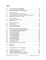
Page 11: ... 500 43 2 7 GrandMaster GM1 Factory Default Settings 44 2 8 Confirming GrandMaster GM1 IP Address Setting 45 2 9 List of Current PTP Related Settings 47 3 1 Interface Connections 56 3 2 Non VLAN Interface Connections 57 3 3 Separate VLAN Interface Connections 58 3 4 Multicast Operational Behavior 59 3 5 BMC Behavior 60 3 6 Show Status Query Example Top Section 63 3 7 Possible State Flow 66 3 8 Pos...

Page 12: ...List of Figures 12 TimeProvider 500 2 0 User s Guide 098 00172 000 Revision A December 2009 ...

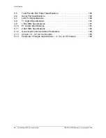
Page 13: ...nt Part Numbers 130 6 1 TimeProvider 500 Mechanical Specifications 133 6 2 TimeProvider 500 Environmental Specifications 134 6 3 TimeProvider 500 Power Specifications 134 6 4 Serial Port Specifications 135 6 5 LAN Port Specifications 135 6 6 1PPS Port Specifications 136 6 7 T1 Output Specifications 136 6 8 1 544 MHz Specifications 137 6 9 10 MHz Specifications 137 6 10 E1 Output Specifications 138...

Page 14: ...Serial Port Specifications 160 C 7 LAN Port Specifications 160 C 8 T1 Output Specifications 161 C 9 1 544 MHz Specifications 161 C 10 E1 Output Specifications 161 C 11 2 048 MHz Specifications 162 C 12 General and Communication Parameters 162 C 13 Version 1 0 2 0 CLI Commands 165 C 14 Parameter Changes and Additions v1 0 to v2 0 Firmware 169 ...

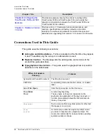
Page 15: ...s the following chapters and appendixes Chapter Title Description Chapter 1 Overview Describes the features and functionality of TimeProvider 500 Chapter 2 Installation Configuration Contains information about the installation site unpacking and installing the system and configuring the unit for operation Chapter 3 Operations Provides descriptions of PTP management interface connections multicast ...

Page 16: ...0 is enabled Chapter C Hardware Version 1 0 Units Provides version 1 0 hardware functional descriptions part numbers specifications and factory defaults and a table identifying the syntax and parameter command changes and additions when upgrading from version 1 0 to version 2 0 firmware When text appears this way it means Symmetricom Product Document The title of a document CRITICAL An operating m...

Page 17: ...ons are installation operation or maintenance procedures practices conditions or statements that if not strictly observed may result in damage to or destruction of the equipment Cautions are also used to indicate a long term health hazard ESD Caution To avoid personal injury and electrostatic discharge ESD damage to equipment do not disregard ESD cautions All ESD cautions use this symbol ESD cauti...

Page 18: ...rovider 500 2 0 User s Guide User s Guide Updates When this manual is updated the updated version will be available for downloading from Symmetricom s Web site After downloading you can view the manual on a computer or print it using Adobe Acrobat Reader Recommendation All recommendations use this symbol Recommendations indicate manufacturer tested methods or known functionality Recommendations co...

Page 19: ... Guide Updates Manual updates are available by logging in to Telecom Solutions Support at http www symmetricom com support online support Note If you are downloading a manual for the first time you will need to register with Symmetricom If you are currently registered login and download the manual update ...

Page 20: ...20 TimeProvider 500 2 0 User s Guide 098 00172 000 Revision A December 2009 How to Use This Guide User s Guide Updates ...

Page 21: ...synchronize to a grandmaster clock To perform the client clock function the TimeProvider 500 uses IEEE 1588 v2 often referred to as Precision Time Protocol PTP as a reference to steer 1PPS 10MHz and T1 and E1 outputs TimeProvider 500 can be configured and monitored using the Command Line Interface CLI accessible locally with the RS232 connection or remotely via a Telnet connection The TimeProvider...

Page 22: ...ardware or software TimeProvider 500 is fully interoperable with Symmetricom s TimeProvider 5000 TimeHub and SSU 2000 IEEE 1588v2 grandmaster products as well as third party grandmaster products that comply with the IEEE 1588v2 protocol standard Key Features The key features supported in this release of the TimeProvider 500 IEEE 1588v2 Translator include Hardware Features 1 Rack Unit RU Package Du...

Page 23: ...hernet networks With the advent of v2 PTP has now been adapted to meet the more sophisticated synchronization requirements of telecommunications applications PTPv2 captures those requirements by providing a set of added capabilities and protocol extensions that allow service providers to fine tune their packet based networks for the stringent timing and synchronization requirements of telecom orie...

Page 24: ... from version 1 0 firmware TOD messages on serial port PTP management via TimeProvider 5000 Proxy including alarms Interface connections support besides supporting interface connections with GrandMasters GM1 and GM2 for receiving and sending PTP packets TimeProvider 500 supports an interface connection with a network device Node Manager for sending and receiving PTP management messages Remote teln...

Page 25: ...oidal 10MHz signal for use in a variety of applications The TimeProvider 500 serves as a translator between timing over packet and traditional SONET SDH networks Set up and monitoring is managed over a serial port or a remote telnet session using the TimeProvider 500 s CLI command set Figure 1 3 TimeProvider 500 Hardware Block Diagram T1 E1 SPAN1 1PPS RS 232 Management 48 VDC Power T1 E1 SPAN2 1PP...

Page 26: ...ersed the unit will not be damaged it simply will not power up Startup power will be less than 9 2 watts Steady state power at a nominal temperature of 25 C is less than 5 3 watts The TimeProvider 500 uses 48 VDC power and is not equipped with a power switch Power to the unit must be controlled by a Branch Circuit Over Current Protection Device to the DC power main Warning To avoid serious persona...

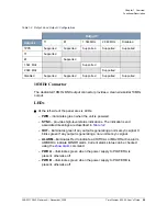
Page 27: ...ed interface while the RJ48 provides a 100 balanced connection Since there are only two E1 T1 channels Figure 1 5 shows which outputs are coupled in terms of frame type Output 1 and Output 4 are coupled together and Output 2 and Output 3 are coupled together Figure 1 5 Output Connector Frametype Coupling The output can be observed on an oscilloscope by connecting directly from the OUT1 or OUT2 BNC...

Page 28: ...if it is not configured for 1PPS Outputs 3 and 2 have a similar coupling For example if output 1 is configured for 1PPS then output 4 can be configured for any signal type except 1PPS If output 1 is configured for E1 then output 4 must be configured as an E1 with the same frame format Table 1 1 and Table 1 2 show the supported combinations of output settings Table 1 1 Output 1 and Output 4 Configu...

Page 29: ...nc signal It blinks green if any output is generating a non normal sync signal ALARM illuminates Red to indicate a CRITICAL or MAJOR active alarm AMBER to indicate MINOR alarm Current alarm status can be checked using the show alarm command PWR A illuminates green when the power supply to POWER A is present otherwise off PWR B illuminates green when the power supply to POWER B is present otherwise...

Page 30: ...configuration and status monitoring capability The RS 232 serial port connection is made through a DE9S female connector This port allows you to connect to a computer using terminal emulation software for remote monitoring and control When connecting to this port use a shielded direct connect cable See Establish Serial Communication on page 40 for default settings Figure 1 6 shows the EIA 232 male...

Page 31: ...ription IEEE 1588 Remote Management Port The RJ 45 connector labeled 1588 is the connection into the network that provides access to the grandmaster clock s access to PTP management functionality see PTP Management on page 54 and firmware upgrade and remote telnet sessions capability Figure 1 7 RJ 45 Connector ...

Page 32: ...32 TimeProvider 500 2 0 User s Guide 098 00172 000 Revision A December 2009 Chapter 1 Overview Functional Description ...

Page 33: ...ustomer service related information Site Survey Before you begin installation determine the shelf location ensure the appropriate power source is available 48 VDC and ensure that the equipment rack is properly grounded Refer to Part Numbers and Return Information on page 99 for more information about ordering kits for rack mounting of the TimeProvider 500 The TimeProvider 500 is designed to mount ...

Page 34: ...ng the BNC connections OUT1 and OUT2 and the Ethernet OUT3 and OUT4 connections Mating connectors for terminating signal wiring Fasteners for mounting the equipment in the rack Digital multimeter or standard voltmeter for verifying power connections to the shelf Laptop computer with serial communications software e g Microsoft Hyperterminal and ProComm Plus for setting system parameters Unpack the...

Page 35: ...ate and set aside small parts which may be packed in the container 6 Remove the accessories from the container 7 Remove the anti static packaging from the unit and accessories 8 Follow the instructions for assembling the rack mounts to the TimeProvider 500 See Part Numbers and Return Information on page 99 for more information 9 Verify that the model and item number shown on the shipping list agre...

Page 36: ...e of the rack environment may be greater than room ambient temperature Therefore consideration should be given to installing the equipment in an environment compatible with the maximum ambient temperature of the TimeProvider 500 which is 65 C Reduced Air Flow Installation of the equipment in a rack should not compromise the amount of air flow required for safe operation of the equipment Mechanical...

Page 37: ...2 TimeProvider 5000 and TimeProvider 500 Rack Mounting Example Ground the Shelf Ground the TimeProvider 500 using the 4mm Grounding Terminal Stud on the unit s panel This Grounding Terminal is marked with the universal ground symbol as shown in Figure 2 3 Figure 2 3 Universal Ground Symbol To make ground connections follow these steps ...

Page 38: ...the rack or grounding rod following Local Electrical Codes Do not connect multiple connectors to the same screw assembly 5 Crimp the other end of the green yellow stripped wire to a inch 6mm UL listed Ring Lug and connect it to the Earth Grounding terminals using an external star lock washer between the Ring Lug and rack or earthing point to be grounded Configuration Setup Setting up the TimeProvi...

Page 39: ...AWG UL1007 wire with the crimp pins supplied Insert Molex pins into the Molex connector provided Wire the other end of the power wires to the Branch Circuit Over Current Protection Device 3 Plug the Molex connector into the TimeProvider 500 and replace the fuse in the Branch Circuit Over Current Protection Device The TimeProvider 500 48 VDC power connector is keyed to only connect one way 4 The co...

Page 40: ...00 settings To logon to the TimeProvider 500 follow these steps 1 Wait for the system to boot 2 At the login prompt type admin then press Enter 3 At the password prompt type symmadmin then press Enter A successful logon responds with the TP 500 prompt Below is an example of what you will see Note The configuration steps throughout this section assumes that the TimeProvider 500 initially has the fa...

Page 41: ...r entry A remote Telnet session will automatically logout whenever 10 minutes elapse without any entry The TimeProvider 500 simultaneously supports up to three remote logon sessions and one serial logon session Configure the TimeProvider 500 IP Address This step establishes the IP address of the TimeProvider 500 The LAN connection from the RJ 45 connector labeled 1588 is used within the PTP domain...

Page 42: ...This section will only use if0 interface 0 which applies to networks not using VLAN A discussion of if1 through if4 interfaces 1 through 4 used for VLAN can be found in Interface Connections on page 55 Using the TimeProvider 500 IP address information in Table 2 2 and the set ip command the following example shows how to set the TimeProvider 500 IP address to Table 2 2 Although the subnet mask is ...

Page 43: ...r 500 Network Communication If not already done a standard RJ45 Ethernet cable should be connected from the TimeProvider 500 port labeled 1588 into the network that will provide connection to the grandmaster clock s See Figure 1 4 TimeProvider 500 connection is 100Base T There are a number of ways to confirm that the TimeProvider 500 is now available on the network The following is a method availa...

Page 44: ...er than 100Base T Configure PTP Settings Now that the TimeProvider 500 is configured for the network configuration of PTP settings can be configured for access to the target grandmaster to establish PTP packet flow Using the show ptp command current PTP configuration data is shown in Figure 2 7 Figure 2 7 GrandMaster GM1 Factory Default Settings Setting the Target Grandmaster IP Address As with th...

Page 45: ...In the example note that the GM2 IP address is shown as 0 0 0 0 which is the factory default unconfigured If the second grandmaster is not used it is recommended that the 0 0 0 0 setting be left unchanged so that the TimeProvider 500 does not attempt communication with a second grandmaster Confirm Connectivity with Grandmaster Clocks To confirm connectivity with GrandMasters GM1 GM2 follow these s...

Page 46: ...place preventing connection If VLAN is being used in the TimeProvider 500 it is essential that the grandmaster also be a member of the same VLAN established by the vlan_config CLI command If VLAN is enabled and two grandmasters are targeted by the TimeProvider 500 then both must be in the same VLAN with the same VLAN ID See Configure PTP Settings for more information Confirm PTP Flow When connecti...

Page 47: ... section of the status response from the TimeProvider 500 as shown in Figure 2 9 See Details for Show Status Function on page 63 for more information about the results of the show status query Configure Frequency Outputs By factory default the TimeProvider 500 produces 2 048 MHz output and 1PPS output If this is the desired output no configuration is needed The show output command identifies the c...

Page 48: ...r OUT1 OUT2 OUT3 or OUT4 using the set output command The selection choices are shown in Table 2 3 For example set OUT2 to e1_ccs with the following command TP 500 set output OUT2 e1_ccs Table 2 3 Output Signal Selections for OUT1 OUT2 OUT3 and OUT4 Selection Output Generated Disable No output clk_2048 2 048MHz square wave default for OUT1 OUT2 OUT4 e1_ccs E1 CCS no CRC4 e1_ccs4 E1 CCS with CRC4 e...

Page 49: ... 500 prompt type set ptp addr mode disable and then press Enter 2 Enable a VLAN interface to use For this example use interface if1 At the TP 500 prompt type set interface if1 enable and then press Enter 3 Configure the IP settings on the desired VLAN interface For more details see Configure the TimeProvider 500 IP Address on page 41 For this example the interface will be set to 192 168 1 12 and a...

Page 50: ...n press Enter 8 The last step is to enable the device for PTP flow At the TP 500 prompt type set ptp addr mode unicast and then press Enter The configuration for VLAN communication between the GrandMaster GM1 and the TimeProvider 500 on interface connection if1 is now completed Installation and Provisioning Checklist To make sure that you have properly installed and provisioned your TimeProvider 5...

Page 51: ...500 Logon Logon to TimeProvider 500 on page 40 Configure TimeProvider 500 IP Address Configure the TimeProvider 500 IP Address on page 41 Confirm TimeProvider 500 Network Communication Confirm TimeProvider 500 Network Communication on page 43 Configure PTP Settings Configure PTP Settings on page 44 Confirm Connectivity with Grandmaster Clocks Confirm Connectivity with Grandmaster Clocks on page 45...

Page 52: ...52 TimeProvider 500 2 0 User s Guide 098 00172 000 Revision A December 2009 Chapter 2 Installation Configuration Installation and Provisioning Checklist ...

Page 53: ...n In This Chapter Introduction PTP Management Interface Connections Multicast Support Time Setting IPDV Details for Show Status Function Flow State Frequency Locked Loop Alarms Events Date Time TimeProvider 500 Logs User Sessions Firmware Upgrade GM2 GrandMaster Introduction Having completed the initial setup and checklist the unit is now ready for operation as a 1588 client clock This section pro...

Page 54: ...p address Only 1 or 2 acceptable masters can be configured These map to GM1 and GM2 The alternate priority field is not used Rebooting the TP500 via PTP management performs an action identical to CLI command reboot system Upgrading the TP500 firmware via PTP management performs an action identical to CLI command upgrade An autonomous PTP message see below is available to provide indication to a no...

Page 55: ...ovider 500 when the GM1 is not responding Node Manager a PTP device that is connected to the network and understands PTP management messages A node manager serves as an interface for PTP message transportation between PTP related devices such as grandmaster clocks and clients Remote CLI Command Access All interface connections are available for VLAN and non VLAN remote telnet sessions Interface Co...

Page 56: ...nagement See Optional Configure VLAN Settings Example for an example of setting an interface connection between the TimeProvider 500 and a GM1 using a VLAN Figure 3 1 Interface Connections if0 if1 if2 if3 if4 For a VLAN connection the if1 if2 if3 and if4 interface connections are available For a non VLAN connection the if0 interface connection is available The TimeProvider 500 s factory default fo...

Page 57: ...ferent VLANs The TimeProvider 500 can be configured for separate VLANs for each of the PTP management devices and remote telnet sessions using the set ip set interface set vlan config and set interface attachments commands as shown in Figure 3 3 When PTP devices GM1 GM2 and the node manager connected to TimeProvider 500 are on the same VLAN and share the same VLAN ID there is no need to use more t...

Page 58: ... is a hybrid of multicast sync and announce messages and unicast delay response messages When selecting multicast mode the TimeProvider 500 joins the multicast within the network system and observes all announce messages Only announce messages from grandmaster clocks in the same domain as the TimeProvider 500 will be assessed for candidacy as the best master clock BMC See Figure 3 4 With hybrid mu...

Page 59: ...nounce comparisons within the multicast environment a sync flow is only allowed from the selected best grandmaster clock See Figure 3 5 Start Multicast Wait for qualified Announce message Wait for SYNC flow Announce message good Signal for Delay flow Wait for Delay flow Normal SYNC flow adequate Delay flow adequate Announce message not qualified SYNC flow not adequate Delay flow not adequate ...

Page 60: ...he TimeProvider 500 will allow management from the configured device If GM1 is not configured and enabled then the TimeProvider 5000 will allow PTP management from the current grandmaster 1 Set the IP address for the TimeProvider 500 interface For this example assume a non VLAN address of 192 168 1 5 with no gateway At the TP 500 prompt type set ip if0 192 168 1 5 netmask 255 255 255 0 gateway 192...

Page 61: ...0 192 168 1 1 Static if1 Disabled Static 66 0 if2 Disabled Static 569 5 if3 Disabled Static 1666 1 if4 Disabled Static 3334 1 Attachments Device interface GM1 if0 GM2 if2 NODE MGR if0 TP 500 show ptp PTP Mode Multicast Hybrid Client MAC address 00 B0 AE 01 22 AD Grand Master 1 IP 0 0 0 0 Grand Master 2 IP 0 0 0 0 Node Management IP 0 0 0 0 Multicast IP 192 168 1 11 Management GM1 Enabled Managemen...

Page 62: ... for forward measurements and delay packets used for the reverse measurements The following measurements can be made Forward and Reverse IPDV below Threshold These results use the set ipdv threshold setting to define the boundary and set ipdv interval value to define the data collection window The results reported one for each flow direction are the percentage of delay variation measurements made ...

Page 63: ... details on how to configure time for the TimeProvider 500 FLL State the current state of the Frequency Locked Loop FLL For details see Frequency Locked Loop on page 67 Reference identifies the device that is exchanging flow with the TimeProvider 500 Note Warm up FLL state duration does not increment until a flow is established TP 500 show status Current Time 21 51 38 11 09 2009 UTC FLL state Norm...

Page 64: ...her the values shown are for the flow direction from the grandmaster to the client or from the client to the grandmaster GM1 shows the number of sync packets being received from the Grandmaster GM1 in the first column and the number of delay response packets being received from the GrandMaster GM1 in the second column Since the default packet rate setting for the TimeProvider 500 is 64 Sync Packet...

Page 65: ...rovider 500 Output TDEV Estimate uses the reference clock model being developed in ITU T SG13 to provide an operational estimate of the output performance of the TimeProvider 500 in terms of peak TDEV stability Flow State If there is an established flow the clock ID of that master clock is shown it can be directly recovered from any PTP packet sent by that master In the example shown there is no G...

Page 66: ...ormal The 1588 packet flow with the grandmaster clock is as expected Suspended The user has disabled 1588 packet flow Table 3 1 Possible Flow State Continued Flow State Description Power Up Suspend Customer Disabled Normal Initializing Check SYNC Message Check Announce Message Wait for GrandMaster to Respond to Signaling Check Delay Message ...

Page 67: ...is established during warm up Unit is getting ready for operation No SYNC Flow None OFF and may blink Amber prior to exit state No Sync packets have been received from master Will remain in this state if there is no flow from master clock Acquiring 20 minutes Blinking Green TimeProvider 500 is receiving sync packets from grandmaster and performing coarse frequency adjustment NORMAL Fast FLL 90 min...

Page 68: ...ach condition has a default severity as shown in Table 5 3 The CLI provides several types of configurable options for each condition See the Set Alarm Commands on page 98 The basic capabilities are Change the severity level of the condition Disable or enable any reporting of the condition Define an amount of time after detection of the condition before it will actually be reported Warmup No Sync F...

Page 69: ...to severity level EVENT 3 The ALARM LED indicates the highest severity level of all conditions that are currently present As with show alarm the ALARM LED will not respond to conditions that have been disabled by user Table 3 3 shows the relationship between highest active severity level and ALARM LED indication When an alarm clears the alarm condition is no longer present and the following occurs...

Page 70: ... and date based on reference described in prior bullet These entries become candidates for the latest entry discovery on the next power up When set clock time is used the date and time are immediately updated Since this places an entry in the logs this provides a new timeline basis for the next power up When PTP flow has been locked the clock is automatically set TimeProvider 500 Logs The TimeProv...

Page 71: ...re information To avoid a possible service call to gain access to the TimeProvider 500 Symmetricom recommends that you record any changes made to the password and store it in a secure location Firmware Upgrade The TimeProvider 500 firmware can be remotely upgraded via FTP See upgrade on page 83 for details Two firmware images are maintained in flash memory to provide a backup in the event of file ...

Page 72: ...sion 2 0 3 Product Version Serial Number r45091 User description doug lab 4 At the TP 500 prompt type upgrade Make sure you have the full file path FTP server IP address server name and password before you begin Example TP 500 upgrade tp500 maincode bin ftp 192 168 5 56 tp5000 Password Response Opening FTP session 220 Welcome to Build Machine FTP service 331 Please specify the password 230 Login s...

Page 73: ...000 erase sector 3a0000 erase sector 3b0000 erase sector 3c0000 erase sector 3d0000 erase sector 3e0000 erase sector 3f0000 erased bank 1 Finished downloading 221 Goodbye TP 500 5 At the TP 500 prompt type reboot system Example TP 500 reboot system Response Rebooting system Bootcode version 1 1 0 Loading Maincode image 1 PTP client TP 500 06 27 41 08 09 2009 221 Login 6 Log on to TimeProvider 500 ...

Page 74: ...mber r45091 User description doug lab The latest firmware version upgraded displays GM2 GrandMaster TimeProvider 500 supports a capability to select from one of two master clocks Use of this feature is easily enabled by providing target addresses for two master clocks See set ptp mgmt on page 108 and set ptp address on page 106 When both are configured to non zero IP addresses the TimeProvider 500...

Page 75: ...ived from both candidate masters and compares information to determine which of the two clocks is preferred Details of the comparison algorithm are beyond the scope of this document but can be seen in Figure 27 of IEEE Std 1588 2008 The show status query shows which of the candidate masters if any is currently being used as the synchronization reference See Details for Show Status Function on page...

Page 76: ...76 TimeProvider 500 2 0 User s Guide 098 00172 000 Revision A December 2009 Chapter 3 Operations GM2 GrandMaster ...

Page 77: ...ge the TimeProvider 500 from either a terminal connected to the EIA 232 serial port or the Ethernet port In This Chapter Overview TimeProvider 500 CLI Command Set Set Commands Set Alarm Commands Set Output Commands Set PTP Commands Show Commands Overview This section describes the CLI command conventions CLI command keyboard usage and command line format Figure 4 1 shows the general structure of t...

Page 78: ...oot set show upgrade alarm alarm config announce auto neg bridge time clock correction eia 232 firewall interface config interface status inventory image led log output ptp status status list temperature tod TimeProvider 500 CLI Command Set alarm config delay alarm config level alarm config proxy alarm config state auto neg bridge time clock time clock timescale clock timezone configuration eia 23...

Page 79: ...plays set Changes settings show Displays settings Continuing with the example typing se and then pressing the Tab key displays set because it is the only possible command Next typing o and then pressing the Tab key displays set output as the only possible command completion When typing s and then pressing the TAB key set output displays Pressing the TAB key again shows the outputs available OUT1 O...

Page 80: ...moved to the position shown by the cursor When you start typing the removed characters are overwritten Command Line Format The command line format is as follows Verb Command Parameter Data EOL Example set output freerun squelch set Verb output Command freerun Parameter squelch Data Command line format description Verb the type of action to be taken with the command Parameter command input that def...

Page 81: ...d configuration logs An entry showing the time that the log was cleared will display at the start of the log Syntax clear log Example TP 500 clear log Response All logs have been cleared Example TP 500 show log event Response Event Log Current time is 23 12 02 11 12 2009 TAI Log 000 23 11 59 11 12 2009 Logs cleared help This command provides a list of first level CLI commands Syntax help Response ...

Page 82: ...command is used to terminate a serial connection session or a remote session via telnet Example 1 Logout from a serial connection example The user is prompted to login TP 500 logout Logging out TP 500 23 13 10 11 12 2009 316 Login Example 2 A logout from a telnet session TP 500 logout Logging out Goodbye Connection to host lost ping This command is updated from version 1 0 This command pings ICMP ...

Page 83: ...ce is not accessible ping 192 168 1 9 Pinging 192 168 1 9 192 168 1 9 Request timed out reboot system This command performs a soft reboot restart of TimeProvider 500 Syntax reboot system Example TP 500 reboot system Response Rebooting system Bootcode version 1 1 1 Loading Maincode image 0 PTP client TP 500 23 14 13 11 12 2009 316 upgrade This command is used to upgrade the TimeProvider 500 firmwar...

Page 84: ...server is anonymous and there is no password Press Enter instead of entering a password For this example to upgrade firmware perform the following steps 1 Type upgrade Maincode bin FTP 192 168 2 3 anonymous and then press Enter 2 At the password prompt leave blank and press Enter Response A response is generated from TimeProvider 500 and after a successful upgrade the message ends with Transfer co...

Page 85: ...enable the TimeProvider 500 displays the available connection speed The disable setting is used when a network does not want to use the Ethernet auto negotiation process Syntax set auto neg enable disable Default Auto neg enable Example set auto neg disable Response Auto negotiation disabled set bridge time This command sets the amount of time in seconds that the TimeProvider 500 remains in bridge...

Page 86: ...utes SS 00 01 59 seconds MM 01 02 12 month DD 01 02 31 day YYYY 2008 2089 year Leading zeros are never required Default 00 00 00 01 01 1970 Example set clock time 09 30 00 date 09 17 2008 Response Time is 09 30 00 09 17 2008 set clock timescale This command in new for version 2 0 Note The set configuration command does not alter the time and date Note The time and date is not updated while TimePro...

Page 87: ...cale set to UTC Default set clock timescale utc Example set clock timescale utc Response Timescale changed to UTC set clock timezone This command in new for version 2 0 This command enables the user to set the timezone offset in hours and minutes for reporting of time in logs and CLI command that show the current time such as the show status or show status list commands Syntax TP 500 set clock tim...

Page 88: ...tax set configuration default factory Default TimeProvider 500 ships with its configuration set to factory Example Sets TimeProvider 500 s configuration to the factory settings set configuration factory Response Setting configuration to factory set eia 232 baud This command is updated from version 1 0 to support changing baud rate This command sets the baud rate on the RS232 MGMT connector Syntax ...

Page 89: ...n See Interface Connections on page 55 for more information Syntax set interface if0 if1 if2 if3 if4 enable disable Default if0 enabled if1 disabled if2 disabled if3 disabled if4 disabled Example set interface if1 enable Response Interface 1 enabled set interface attachments This command is new for version 2 0 to support interface connections In version 1 0 there was only a single interface connec...

Page 90: ...esting which interface is being used for the selected PTP attachment TP 500 set interface attachments node mgr if0 Attaches NODE MGR to interface 0 if1 Attaches NODE MGR to interface 1 if2 Attaches NODE MGR to interface 2 if3 Attaches NODE MGR to interface 3 if4 Attaches NODE MGR to interface 4 TP 500 set interface attachments node mgr if3 Response NODE MGR attached to interface 3 Note Telnet sess...

Page 91: ...if2 if3 if4 ip address netmask netmask gateway gateway Range Range for all settings 0 1 255 Default set configuration factory configures the TimeProvider 500 to the following settings for individual interface connections if0 address 192 168 1 9 if1 address 10 1 1 1 if2 address 10 1 2 1 if3 address 10 1 3 1 if4 address 10 1 4 1 for all interface connections if0 if1 if2 if3 if4 Netmask 255 255 255 0...

Page 92: ...et ipdv pacing This command in new for version 2 0 This command configures the observation pacing factor for the forward and reverse IPDV inter packet jitter measurement The pacing factor identifies how often to select a data point for the jitter analysis For example if pacing value is 128 every 128th sample will be used for jitter assessment in either flow direction IPDV settings and results can ...

Page 93: ...e IPDV data Set ipdv reset Response Reset IPDV data set ipdv threshold This command in new for version 2 0 This command sets the threshold level to be used for IPDV percent below threshold results The same threshold is used for the forward and reverse results IPDV settings and results can be shown with the show status list command Syntax Set ipdv threshold threshold_value Range 0 to 1000000 000 us...

Page 94: ...f0 if1 if2 if3 if4 static Example set ip mode if2 dhcp Response Interface 2 IP mode set to dhcp set tod This command is new for version 2 0 This command controls whether or not TOD Time of Day output is generated on the RS232 serial port When set to enable TOD is generated each second TOD format is controlled by the set tod format command When enabled TOD is unconditionally generated Syntax Set to...

Page 95: ...e applied to the UTC time but not the TAI time Syntax Set tod format NMEA T1 Example set tod format T1 Response TOD format changed to timecode 1 set tod timescale This command is new for version 2 0 This command sets the timescale to be used in TOD output This setting only affects the timescale used for TOD messages and does not affect the timescale used in logs or other time reporting which is co...

Page 96: ...ters a through z and numbers 0 through 9 Password Range Must be between 8 32 characters in length All characters must be printable ASCII ASCII decimal values 33 126 and a comma semicolon and colon are never allowed 2 characters must be non alphabetic For example a number would qualify 1 character must be non alphanumeric would qualify Default User Name admin Default Password symmadmin Example TP 5...

Page 97: ...a user enters a user description in uppercase letters Syntax TP 500 set udesc Example TP 500 set udesc ABCDE Response User data set to ABCDE Using the show inventory command the new user description settings are shown TP 500 show inventory Product Number 090 03863 02 Firmware Version 2 0 0 Product Version Serial Number r45091 User description ABCDE set vlan config This command is updated from vers...

Page 98: ...ity 0 Example Sets VLAN ID to 22 and priority to 6 set vlan config 22 priority 6 Response VLAN ID set to 22 and priority to 6 Set Alarm Commands The set alarm command set allows you to enable or disable reporting of selected alarms configure the severity level of alarms and the delay before an alarm is reported Alarm number mapping is shown in Table 5 3 Note The set configuration factory command w...

Page 99: ...s set alarm config level The number of alarms has increased from 14 to 19 in version 2 0 This command configures the severity level of the selected alarm The alarm_num option allows you to select an individual alarm See show alarm on page 111 for more information The selected severity may change the alarm LED indication see Alarm System Messages on page 126 for details Syntax set alarm config leve...

Page 100: ...ider 500 This would allow the receiving device to either handle the alarm or forward it via an SNMP trap Syntax set alarm config proxy alarm alarm_num enable disable Range alarm_num 0 1 N N currently 19 Default See Alarm System Messages for default severities Example Sets all alarms to minor severity set alarm config proxy alarm 9 enable Response Alarm 9 proxy is enabled set alarm config state The...

Page 101: ...3 2 ais using this setting will cause the appropriate Alarm Indication Signal AIS to be generated when in freerun mode If set output signaltype is set to disable no AIS output will be generated squelch using this setting causes the outputs to be turned off when in freerun mode regardless of the set output signaltype settings Syntax set output freerun ais on squelch Default Note To see changes made...

Page 102: ... HDB3 encoding set output hdb3 disable Response HDB3 set to disable set output holdover This command sets specific output behavior when TimeProvider 500 is in holdover mode The following parameters are used when specifying output behavior on this command enables the set output signaltype when TimeProvider 500 is in holdover mode ais this command enables the appropriate AIS to be generated when in ...

Page 103: ...27 and Configure Frequency Outputs on page 47 for more information on these outputs and the coupling between them Syntax set output out1 out2 out3 out4 signaltype Where out1 1pps clk_1544 clk_2048 e1_ais e1_cas e1_cas4 e1_ccs e1_ccs4 disable t1_sf t1_esf t1_iso_pulse out2 1pps clk_1544 clk_2048 e1_ais e1_cas e1_cas4 e1_ccs e1_ccs4 disable t1_sf t1_esf t1_iso_pulse out3 clk_1544 clk_2048 e1_ais e1_...

Page 104: ...coupled Default standard Example set output pps mode standard Response Setting PPS mode to standard set output pps offset This is a new command for 2 0 This command offsets the time position of the 1PPS output The output is adjusted in time compared to where it would be positioned otherwise by the configured value The rising edge is the on time edge Any 1PPS output is affected equally by this sett...

Page 105: ...tput pps offset 10000 Response Setting 1PPS offset to 10000 ns set output pps width This command sets the positive pulse width of the 1PPS output The rising edge is the on time edge The position of the pulse can be adjusted using set output pps offset Syntax width in ns 100 500000000 ns in steps of 1ns Default width in ns 100 000 000 100 ms Example To set any 1PPS output width to 10 µs set output ...

Page 106: ...ynchronize sync announce and delay response messages with a grandmaster clock See Multicast Support for more information Syntax set ptp addr mode disable multicast hybrid unicast Default enabled Example set ptp addr mode to unicast Response PTP mode set to Unicast set ptp address This command configures the IP address of the selected external device The external device is either the GrandMaster cl...

Page 107: ... ptp domain This command sets the ptp domain value for TimeProvider 500 Syntax set ptp domain domain_number Range domain_number 0 1 255 Default domain_number 0 Example Sets the domain number to 3 set ptp domain 3 Response Domain set to 3 Note The TimeProvider 500 will not attempt communications with a device if this setting is 0 0 0 0 Note The set configuration factory command will reset the IP ad...

Page 108: ... value to 16 set dscp to 16 Response DSCP set to 16 set ptp mgmt This command is new for version 2 0 The command controls whether the selected PTP device allows PTP management This provides user control on which external devices are allowed to configure and control actions in the TimeProvider 500 See PTP Management Syntax Set ptp mgmt gm1 gm2 node mgr enable disable Default gm1 enable gm2 enable n...

Page 109: ...nfigured for PPS coupled mode see set output pps mode time services are disabled Syntax set ptp transport dsl ethernet microwave sonet Range TP 500 set ptp transport dsl Sets PTP transport mode to DSL ethernet Sets PTP transport mode to Ethernet microwave Sets PTP transport mode to microwave sonet Sets PTP transport mode to SONET Example TP 500 set ptp transport dsl Response Setting PTP transport ...

Page 110: ...lish between a grandmaster clock server and itself Syntax set ptp unicast lease int lease_duration Range lease_duration 10 11 3000 seconds Default 300 seconds Example Sets the lease duration to 200 seconds set ptp unicast lease int 200 Response PTP lease set to 200 seconds set ptp unicast sync int The sync rate range has changed for version 2 0 This command sets the TimeProvider 500 requested unic...

Page 111: ...show alarm This command provides a list of active alarms Syntax show alarm Response ID Severity Time Date Description 0 MAJOR 00 00 01 01 01 1970 Lost communication with GM 2 MAJOR 00 00 01 01 01 1970 Free run 3 MAJOR 00 00 01 01 01 1970 Sync packet rate low 4 MAJOR 00 00 01 01 01 1970 Delay packet rate low 9 MAJOR 00 00 01 01 01 1970 LINK loss of signal show alarm config This command provides a t...

Page 112: ... 12 3 ENABLED DISABLED MAJOR Announce Timeout GM2 13 3 ENABLED DISABLED MAJOR Signaling Ack Timeout GM1 14 3 ENABLED DISABLED MAJOR Signaling Ack Timeout GM2 15 3 ENABLED ENABLED EVENT Upgrade TP500 firmware 16 3 ENABLED DISABLED MAJOR Power Supply A 17 3 ENABLED DISABLED MAJOR Power Supply B 18 3 ENABLED DISABLED MAJOR Packet RTD too large 19 3 ENABLED DISABLED MAJOR Excessive transients show ann...

Page 113: ... is Disabled show bridge time This command shows the current bridge time setting This setting determines how long the TimeProvider 500 will remain in BRIDGING FLL state before a transition into HOLDOVER state See Table 3 2 and Figure 3 8 Syntax show bridge time Response Bridging time set to 420 show clock This command is changed from version 1 0 This command shows the TimeProvider 500 s time show ...

Page 114: ...his command shows average correction value in PTP packet Syntax TP 500 show correction Response GM forward corr 0 ns Acc GM forward corr 0 ns Delay corr 0 ns show eia 232 This command shows the baud setting for the serial port on theTimeProvider 500 Syntax show eia 232 baud Response Baud 57600 Parity none Data bits 8 show firewall This command shows the current firewall settings Syntax TP 500 show...

Page 115: ...sabled 10 1 2 1 255 255 255 0 0 0 0 0 Static 3 0 if3 Disabled 10 1 3 1 255 255 255 0 0 0 0 0 Static 4 0 if4 Disabled 10 1 4 1 255 255 255 0 0 0 0 0 Static 5 0 Attachments Device interface GM1 if0 GM2 if0 NODE MGR if0 show interface status This command shows which interface configurations are recognized by the network system This command is similar to the show interface config command The differenc...

Page 116: ...re Version 2 0 0 Product Version Serial Number r45091 User description doug lab show image This commands shows information about firmware images that are currently stored in flash memory Syntax show image Default at Shipment Images 0 and 1 contain the most recent TimeProvider 500 firmware released at the time of shipment Example show image Response Image 0 rev 1 0 27 size 702563 bytes checksum 0xF...

Page 117: ... command shows the content of the selected log The configuration log provides history of configuration changes and the event log provides a history of alarms and events event minor major and critical levels The show event log lists up to 200 entries numbered from 000 to 199 The sequence of the records in the log is first in and first out The latest entry is assigned the highest number in the log S...

Page 118: ...y of signal output settings Syntax show output Example TP 500 show output Response TP 500 show output Output 1 type 2 048 MHz Clock Output 2 type 1PPS Output 3 type 2 048 MHz Clock Output 4 type 2 048 MHz Clock HDB3 Enabled Freerun output mode on Holdover output mode on 1PPS offset 2984 ns 1PPS pulse width 100000000 ns 1PPS mode standard show ptp This command provides a summary of all PTP related ...

Page 119: ... 500 show status Example TP 500 show status Response Current Time 21 51 38 11 09 2009 UTC FLL state Normal FLL 2840 min Temperature Reference GM2 Avg 41 01 C Correction Freq 10 12 ppb Min 40 88 C Phase 0 00 ppb Max 41 06 C Output MDEV Estimate 0 0002 ppb 5min 55 37 mC Residual Phase Error 2377 13 ns 60min 166 04 mC Minimal RTD 12 57 usec Flow Direction GM to client client to GM GM1 pkts s 0 0 GM2 ...

Page 120: ... Reverse Flow Operational MAFE ppb 0 01 Reverse Flow Min Cluster Width ns 100 0 Reverse Flow Mode Width ns 200 0 Correction Frequency ppb 10 12 Phase correction ppb 0 00 Output TDEV Estimate ns 1 80 Output MDEV Estimate ppb 0 00 Residual phase error ns 2377 13 Minimal RTD us 12 57 Operational Temperature Max deg C 41 06 Operational Temperature Min deg C 40 88 Operational Temperature Avg deg C 41 0...

Page 121: ...he TimeProvider 500 The data presented shows temperature behavior and conditions Temperature data is also provided in the show status command Syntax show temperature Response Temperature 30 65 C show tod This command shows TOD status TOD format and TOD timescale parameters based on the settings configured with the set tod command Syntax show tod Response TOD status Disabled TOD format T1 TOD times...

Page 122: ...122 TimeProvider 500 2 0 User s Guide 098 00172 000 Revision A December 2009 Chapter 4 CLI Commands Show Commands ...

Page 123: ...tion TimeProvider 500 System and Accessory Part Numbers Returning the TimeProvider 500 Contacting Symmetricom Global Services User Manual Updates Preventive Maintenance The TimeProvider 500 requires minimal preventive maintenance Ensure the unit is not exposed to hazards such as direct sunlight open windows water or extreme heat Caution To avoid electromagnetic discharge damage to the circuitry ne...

Page 124: ...ent Refer to the National Electric Code ANSI NFPA70 or per the application code in the country of installation for more information Table 5 1 Preventive Maintenance Item Inspection Corrective Action Interval Chassis Inspect for dirt or foreign material Clean the exterior of chassis with a soft dry cloth Periodically Cables Inspect for pinched worn or damaged cable Replace pinched worn or damaged c...

Page 125: ... sychronization packets from the grandmaster clock and performing frequency adjustments Green Performance margins are stable or abnormal packet flow is observed such as loss of synchronization flow or significant load change Amber TimeProvider 500 is no longer using synchronization flow from the grandmaster clock to control the outputs T1 E1 signal activity OUT Off No output Green A normal sync si...

Page 126: ...larm The alarm number alarm_num is used in the CLI commands to alter delay enable status or define alarm severity if desired Table 5 3 Alarm System Messages Description Alarm Number Default Severity Level MsgText Corrective Action The TimeProvider 500 is in holdover mode 0 Major Holdover See Grandmaster Clock Link Corrective Action on page 130 The TimeProvider 500 is in free run mode This is a nor...

Page 127: ...Major Outputs disabled To enable output signals change the output signaltype to a setting other than disable PTP is disabled via the set ptp state command This alarm provides a reminder that the TimeProvider 500 will not operate normally with this setting 7 Major PTP disabled See Grandmaster Clock Link Corrective Action on page 130 The sync packet rate from the grandmaster has fallen below the exp...

Page 128: ...IP address of both possible grandmaster clocks is set to 0 0 0 0 With an 0 0 0 0 IP address setting TimeProvider 500 is not expecting packet flow signals from the possible grandmaster clocks 10 Major Delay packet rate low See Grandmaster Clock Link Corrective Action on page 130 and verify that the grandmaster clock is ready for connection The announce messages from the grandmaster clock are disqua...

Page 129: ...ndMaster clock signaling acknowledgements have timed out This means that signaling requests from TimeProvider 500 are not being acknowledged by the grandmaster clock 14 Major Signaling Ack Timeout GM2 See Grandmaster Clock Link Corrective Action on page 130 Firmware upgrade is in process 15 Event Upgrade TP500 firmware N A The power is not being supplied at PWR A 16 Major Power Supply A Verify tha...

Page 130: ...ovider 500 System and Accessory Part Numbers This section provides part numbers and accessories available for the TimeProvider 500 Returning the TimeProvider 500 You should return the equipment to Symmetricom only after you have exhausted the troubleshooting procedures described in this user guide or if Symmetricom Global Services has advised you to return the unit Table 5 4 Component Part Numbers...

Page 131: ...est an RMA on the internet at www symmetricom com Support req_repair htm Retain the assigned RMA number for future reference 2 Provide a description of the problem product item number serial number and warranty expiration date 3 Provide the return shipping information customer field contact address telephone number and so forth 4 Ship the product to Symmetricom transportation prepaid and insured w...

Page 132: ...il emeasupport symmetricom com Internet http www symmetricom com User Manual Updates From time to time this manual may be updated The updated version of the manual will be available for downloading in electronic form via the Internet After downloading the manual can be viewed on a computer or printed out Manual updates are available by logging in to Telecom Solutions Support at http www symmetrico...

Page 133: ...tory Defaults Electromagnetic Environment Regulatory Requirements Component Specifications This section provides the specifications for the TimeProvider 500 components and input and output signals Mechanical Table 6 1 TimeProvider 500 Mechanical Specifications Parameter Description Mounting 19 in 48cm Rack Rack Mounting Position Front mounting location unit protrudes 0 75 in 4 445cm Width 8 53 in ...

Page 134: ...perating Temperature 5 to 65 C 23 to 149 F Storage Temperature 40 to 70 C 40 to 158 F Operating Humidity 5 to 93 RH Storage Humidity 10 to 100 RH Table 6 3 TimeProvider 500 Power Specifications Parameter Description DC Input 48 VDC 60 VDC Nominal 0 110A current 48V Operating range 40 VDC to 72 VDC 0 175A warm up 48V 0 100A operating 48V Branch Circuit Over Current Protection Device 1 0 A DC Power ...

Page 135: ...ype 9 pin female D connector Connector Label RS232 MGMT Interface RS 232 data terminal equipment DTE Baud Rate 57 6 Kbps Data Bits 8 Parity Bit None Stop Bits 1 Flow Control None Timeout Approximately 60 minutes Table 6 5 LAN Port Specifications Parameter Description Connector Type RJ 45 Connector Label 1588 Speed 100 Mbps Interface IEEE 1588v2 and telnet Timeout Approximately 10 minutes applies f...

Page 136: ...lts Connector Label OUT1 OUT2 Impedance 50 Pulse Width 100 ns 500 ms Risetime 20 ns Table 6 7 T1 Output Specifications Parameter Specification Connector Type BNC RJ48C Connector Label OUT1 OUT2 OUT3 OUT4 Framing user selectable D4 Super Frame SF Extended Super Frame ESF Signal Waveshape Framed all ones Alternate Mark Inversion AMI per ANSI T1 102 and ITU T Rec G 703 Pulse Amplitude 2 4 to 3 6 volt...

Page 137: ...BNC RJ48C Connector Label OUT1 OUT2 OUT3 OUT4 Amplitude 2 4 to 3 6 volts peak into 100 Wave Shape Square Wave Termination Impedance 100 Table 6 9 10 MHz Specifications Parameter Specification Connector Type BNC Connector Label 10 MHz Amplitude 7 5 dBm to 1 5 dBm nominal into 50 Wave Shape Sinusoidal Termination Impedance 50 Phase Noise 1Hz 60 dBc Hz 10 Hz 90 dBc Hz 100 Hz 110 dBc Hz 1 kHz 120 dBc ...

Page 138: ...the test Table 6 10 E1 Output Specifications Parameter Specification Connector Type BNC RJ48C Connector Label OUT1 OUT2 OUT3 OUT4 Framing user selectable CAS CCS CAS4 CCS4 Signal Waveshape Framed all ones Alternate Mark Inversion AMI Per ITU T Rec G 703 Sec 9 Pulse Amplitude 2 7 to 3 3 volts peak into 120 2 13 to 2 6 volts peak into 75 Termination Impedance 120 5 balanced 75 5 unbalanced Table 6 1...

Page 139: ...IE Test Threshold Table 6 12 Typical Performance Test Cases MTIE Test Threshold Fractional Frequency Offset 1PPS Output compared with Grandmaster PPS Advanced 8261 based tests more severe conditions See Figure 6 1 1ppb 3µs 8261 based tests 5 switches See Figure 6 1 1ppb 1µs Transport includes microwave SHDSL or TDM over packet N A 5ppb N A ...

Page 140: ...wall Allowed for telnet ICMP Allowed Blocked Freerun Output ON ais on squelch Gateway Address 0 0 0 0 Valid IPv4 Address GM1 IP Address 192 168 1 11 Valid IPv4 Address GM2 IP Address 0 0 0 0 Valid IPv4 Address HDB3 Enabled Enable Disable Holdover Output ON ais on squelch IP Address 192 168 1 9 non VLAN Valid IPv4 address IP Mode Static DHCP Static Lease Duration 300 seconds 10 3000 seconds Network...

Page 141: ...8 clk_2048 e1_cas e1_cas4 e1_ccs e1_ccs4 e1_ais 1_sf t1_esf clk_1544 t1_iso_pulse Sync Rate 64 pkt second 16 32 64 pkt sec User Name admin 20 ASCII characters User Password symmadmin 32 ASCII characters a minimum of 8 VLAN Interfaces Disabled Enable Disable VLAN ID if1 2 if2 3 if3 4 if4 5 1 4094 VLAN Priority 0 0 7 Note When using the set configuration factory command the User Name and User Passwo...

Page 142: ...24 Class B KN 55022 24 KCC Class B EMC IMMUNITY MEETS CRITERIA A EN61000 4 2 ESD EN61000 4 3 RADIATED IMMUNITY EN61000 4 4 ELECTRICAL FAST TRANCIENT BURST EN61000 4 5 SURGE EN61000 4 6 CONDUCTED IMMUNITY NEBS EMC Fully Compliant NEBS ESL Partially Compliant Regulatory Requirements Symmetricom is certified with the following safety compliant certificates UL cUL CB Scheme CE Mark ...

Page 143: ...RMC Message header 122356 UTC value hhmmss A Status A active V void 0000 0000 N Latitude north Normally fixed to zero optionally grandmaster s position 00000 0000 W Longitude west Normally fixed to zero optionally grandmaster s position 0 0 Speed over ground fixed to zero 0 0 Track angle fixed to zero 120508 Date ddmmyy A A autonomous D differential E estimated S simulation N not valid F6 NMEA Che...

Page 144: ...1 2 bytes ASCII Mode string T1 3 8 003125 6 bytes ASCII time value hhmmss can be set to UTC local GPS or TAI timescale 9 16 11182009 8 bytes ASCII date value ddmmyyyy 17 18 00 2 bytes ASCII FOM Output TDEV Estimate 100 0 19 20 03 2 bytes ASCII Status Word Bit 7 1 pending leap sec Bit 6 1 pending leap sec Bit 5 not used Bit 4 not used Bit 3 not used Bit 2 Bit 0 0 FLL_UNKNOWN 1 FLL_WARMUP 2 FLL_FAST...

Page 145: ...PTP disabled 8 Sync packet rate low GM1 9 Sync packet rate low GM2 10 Delay packet rate low 11 Announce Timeout GM1 12 Announce Timeout GM2 13 Signaling Ack Timeout GM1 14 Signaling Ack Timeout GM2 15 Upgrade TP500 firmware 16 Power Supply A 17 Power Supply B 18 Packet RTD too large 19 Excessive transients 29 31 22 2 bytes ASCII UTC TAI offset Hex 00 to FF 32 33 53 2 bytes ASCII Checksum CRC from ...

Page 146: ...146 TimeProvider 500 2 0 User s Guide 098 00172 000 Revision A December 2009 T1 Format ...

Page 147: ...r 500 Connect to Craft Port Use serial cable to connect Craft port to serial port of laptop computer Connect to Craft Port Use serial cable to connect Craft port to serial port of laptop computer Serial Communication Establish serial communication with TP5000 using terminal emulation All Programs Accessories Communication HyperTerminal COM1 port 8 data bits 1 stop bit no parity 57 600 baud rate no...

Page 148: ...mode for all the interface connections is static Perform the following steps 1 At the TP 500 prompt type set ip if0 192 168 1 22 netmask 255 255 255 0 gateway 192 168 1 1 enter 2 To verify IP change at the TP 500 prompt type show interface config enter Configure Dynamic Management IP Address The Ethernet cable should already be connected and the DHCP server configured Perform the following steps 1...

Page 149: ...rm the following step 1 At the TP5000 prompt type show ip status imc enter Confirm Grandmaster Address and PTP Configuration Perform the following step 1 At the TP 500 prompt type show ptp enter Enable Firewall for Telnet Perform the following steps 1 At the TP5000 prompt type set firewall imc telnet allow enter 2 At the TP5000 prompt type set ip imc restart enter Connect Through an Ethernet LAN U...

Page 150: ...pt type set redundancy port ioc1 enable enter Independent Ports Perform the following steps 1 At the TP5000 prompt type set redundancy port ioc1 disable enter 2 At the TP5000 prompt type set ip ioc1 1 address 192 168 1 15 netmask 255 255 255 0 gateway 192 168 1 1 enter 3 At the TP5000 prompt type set ip ioc1 1 restart enter 4 At the TP5000 prompt type set ip ioc1 2 address 192 168 2 15 netmask 255...

Page 151: ...ponse Ping ioc 1 success To verify which clients are connected to a specific port lists clients and their settings and addresses perform the following step 1 At the TP5000 prompt type show ptp client ioc y y is the port the client is pointed to for the grandmaster Confirm Network Communication between TimeProvider 5000 and TimeProvider 500 Connect the Ethernet cable from the TimeProvider 500 1588 ...

Page 152: ...152 TimeProvider 500 2 0 User s Guide 098 00172 000 Revision A December 2009 TimeProvider 5000 and 500 Configuration Example ...

Page 153: ... differences in similar commands when upgrading from version 1 0 to version 2 0 firmware In This Appendix Version 1 0 Component Functional Description Version 1 0 System and Accessory Part Numbers Version 1 0 Component Specifications Version 1 0 Factory Defaults Version 1 0 Electromagnetic Environment Version 1 0 Regulatory Requirements Syntax Changes and Additions Version 1 0 to Version 2 0 Firmw...

Page 154: ...the power connection is reversed the unit will not be damaged it simply will not power up Startup power will be 17 watts Steady state power nominal 25 C 9 6 watts The TimeProvider 500 uses 48 VDC power and is not equipped with a power switch Power to the unit must be controlled by a Branch Circuit Over Current Protection Device to the DC power main Warning To avoid serious personal injury or death...

Page 155: ...led in the CLI command set output signaltype on page 71 Both outputs must be the same signal type There are two independent separately driven outputs labeled SPAN1 and SPAN2 For differential connection to either output use the appropriate RJ48C connection shown in Figure SPAN1 is the upper connection and SPAN2 is the lower connection For single ended connection to either output use the BNC connect...

Page 156: ...rent alarm status can be checked using the show alarm command For more information see the CLI command show alarm on page 76 Chassis Ground Above the LEDs is a connection to chassis ground A 4mm Grounding Terminal Stud is located on the TimeProvider 500 s front panel The grounding terminal is marked with the universal ground symbol Note The outputs from the left BNC and lower RJ48C connection both...

Page 157: ...ulation software for remote monitoring and control When connecting to this port use a shielded direct connect cable See Establish Serial Communication on page 40 for default settings Figure C 5 Serial Port Male Connector Pins Table C 1 describes the EIA 232 connector pin assignments for the serial port IEEE 1588 Remote Management Port The RJ 45 connector labeled 1588 is the connection into the net...

Page 158: ...nent Part Numbers Item Part Number TimeProvider 500 IEEE 1588v2 Translator Kit 990 03863 01 Power Connector and Pins included with part number 990 03863 01 093 00063 000 TimeProvider 500 19 Rack Mount Kit 093 00090 000 TimeProvider 500 19 Dual Rack Mount Kit 093 00069 000 21 Mounting Adapter Bracket Kit 093 00011 000 23 Mounting Adapter Bracket Kit 093 00012 000 Table C 3 TimeProvider 500 Mechanic...

Page 159: ... Operating Temperature 5 to 55 C 23 to 131 F Storage Temperature 40 to 70 C 40 to 158 F Operating Humidity 5 to 90 RH Storage Humidity 10 to 100 RH Table C 5 TimeProvider 500 Power Specifications Parameter Description DC Input 48 VDC 60VDC Nominal 0 20A current 48V Operating range 40 VDC to 72 VDC 0 280A warm up 48V 0 180A operating 48V Branch Circuit Over Current Protection Device 1 0 A DC Power ...

Page 160: ...Type 9 pin female D connector Connector Label RS232 MGMT Interface RS 232 data terminal equipment DTE Baud Rate 57 6 Kbps Data Bits 8 Parity Bit None Stop Bits 1 Flow Control None Timeout Approximately 60 minutes Table C 7 LAN Port Specifications Parameter Description Connector Type RJ 45 Connector Label 1588 Speed 100 Mbps Interface IEEE 1588v2 and telnet Timeout Approximately 10 minutes applies ...

Page 161: ... 6 volts peak into 100 Termination Impedance 100 5 balanced Table C 9 1 544 MHz Specifications Parameter Specification Amplitude 1 0 to 1 9 volts peak 1 5 volts peak nominal into 120 0 8 to 1 5 volts peak 1 2 volts peak nominal into 75 Wave Shape Square Wave Termination Impedance 75 Table C 10 E1 Output Specifications Parameter Specification Framing user selectable CAS CCS CAS4 CCS4 Signal Wavesha...

Page 162: ...tion default values Table C 11 2 048 MHz Specifications Parameter Specification Amplitude 1 0 to 1 9 volts peak 1 5 volts peak nominal into 120 0 8 to 1 5 volts peak 1 2 volts peak nominal into 75 Wave Shape Square Wave Termination Impedance 75 Table C 12 General and Communication Parameters Description Default Value Value Range Acc Grandmaster IP Address 0 0 0 0 Valid IPv4 Address Alarm Delay 3 s...

Page 163: ...e E1 T1 2 048 MHz e1_2048m E1 signal type e1_2048m e1_cas e1_cas4 e1_ccs e1_ccs4 e1_ais T1 signal type t1_sf t1_esf t1_1544m t1_iso_pulse Sync Rate 64 pkt second 32 64 128 pkt sec User Name admin 20 ASCII characters User Password symmadmin 32 ASCII characters a minimum of 8 VLAN Disabled Enable Disable VLAN ID 2 1 4094 VLAN Priority 0 0 1 7 Note When using the set configuration factory CLI command...

Page 164: ...lass B ICES 003 Class B VCCI Class A AS NZS CISPR 22 Class B ETSI 300 386 Class B EN 55022 24 Class B KN 55022 24 KCC Class B EMC IMMUNITY MEETS CRITERIA A EN61000 4 2 ESD EN61000 4 3 RADIATED IMMUNITY EN61000 4 4 ELECTRICAL FAST TRANCIENT BURST EN61000 4 5 SURGE EN61000 4 6 CONDUCTED IMMUNITY Version 1 0 Regulatory Requirements Symmetricom is certified with the following safety compliant certific...

Page 165: ...page 81 for CLI command details Table C 13 Version 1 0 2 0 CLI Commands Version 1 0 Version 2 0 Description set alarm config proxy New for 2 0 set auto neg New for 2 0 set clock timescale New for 2 0 set clock timezone New for 2 0 set interface New for 2 0 set interface attachments New for 2 0 set ipdv New for 2 0 set output pps offset New for 2 0 set output pps mode New for 2 0 set output pps wid...

Page 166: ...k time The result will be overwritten if there is a qualified master clock providing time set configuration set configuration Syntax unchanged in 2 0 set eia 232 set eia 232 baud The RS232 MGMT connector baud rate can be configured in 2 0 the baud rate was fixed at 57600 in 1 0 set firewall set firewall Syntax unchanged in 2 0 set ip address set ip Syntax for configuring IP address information is ...

Page 167: ...st in 2 0 set ptp unicast announce int set ptp unicast announce int Syntax unchanged in 2 0 set ptp unicast lease int set ptp unicast lease int Syntax unchanged in 2 0 set ptp unicast sync int set ptp unicast sync int The settable range has changed in 2 0 to 16 32 64 set user set user Syntax unchanged in 2 0 set vlan config set vlan config Changed for 2 0 to support connection interfaces set vlan ...

Page 168: ... unchanged However the PWD LED is used for both POWER A and POWER B show log show log Syntax unchanged in 2 0 show output show output Enhanced for 2 0 It includes configuration status for 2 0 output capabilities Output signals E1_2048m and T1_1544 have changed to clk_2048 and clk_1544 show ptp show ptp Changed for 2 0 to support PTP or general management options show status show status Changed and...

Page 169: ...rsion 2 0 Firmware set alarm config delay Any value 3 set alarm config level Any value MAJOR except 15 is EVENT set alarm config state Any value Enable set alarm config proxy N A Disable except for 0 1 3 4 15 set auto neg N A True set bridge time n n 120 not greater than 86400 set clock timescale N A UTC set clock timezone N A 0 Set interface Non VLAN address Enable only if0 Make if0 ip addressing...

Page 170: ...mt N A All enabled set ptp address node mgr N A 0 0 0 0 set ptp transport N A Ethernet set tod enable disable N A Disable set tod timescale N A TAI set tod format N A T1 set udesc N A empty string Table C 14 Parameter Changes and Additions v1 0 to v2 0 Firmware Continued Parameter Release 1 0 Firmware After Upgrade from Version 1 0 to Version 2 0 Firmware ...

Page 171: ...85 set clock time 86 set clock timescale 86 set clock timezone offscale 87 set configuration 88 set eia 232 baud 88 set firewall 88 set interface 89 set interface attachments 89 set ip 91 set ip mode 94 set output 103 set output freerun 101 set output hdb3 102 set output holdover 102 set output pps mode 104 set output pps offset 104 set output pps width 105 set ptp address 106 set ptp domain 107 s...

Page 172: ...tput connectors 27 G GM2 acceptable grandmaster 74 H help command 81 holdover specifications 138 162 I IEEE 1588 remote management port 31 installation 33 installation checklist 50 installing grounding the shelf 37 rack mounting 36 site survey 33 unpacking 34 interface connections 55 if0 if1 if2 if3 if4 56 ptp management devices 55 reviewing interface configurations 58 L LED indicator descriptions...

Page 173: ...auto neg command 113 show bridge time command 113 show clock command 113 show commands 111 show correction command 114 show eia 232 command 114 show firewall command 114 show image command 116 show interface config command 115 show interface status command 115 show inventory command 116 show led command 117 show log command 117 show output command 118 show ptp command 118 show status command 119 s...

Page 174: ...Index W W 174 TimeProvider 500 2 0 User s Guide 098 00172 000 Revision A December 2009 ...

Reviews: