098-00172-000 Revision A – December, 2009
TimeProvider 500 2.0 User’s Guide
67
Chapter 3 Operations
Frequency Locked Loop
Frequency Locked Loop
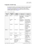
The TimeProvider 500 drives a state sequence that allows the operational status of
the Frequency Locked Loop (FLL) to be observed. These can be viewed via the
CLI command query.
lists the FLL states, transition
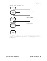
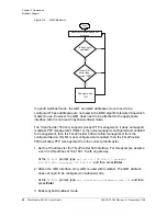
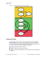
conditions, and SYNC LED impact. The possible sequential flow of frequency
locked-loop states is shown in
.
Table 3-2. Frequency Locked-Loop State
TimeProvider
500 State
Current FLL
State
Typical
Duration
SYNC LED
Comment
FREERUN
Warm-up
~2-3 minutes
OFF initially and
then may blink.
Amber if flow is
established during
warm-up.
Unit is getting ready
for operation.
No SYNC
Flow
None
OFF and may
blink Amber prior
to exit state.
No Sync packets
have been received
from master. Will
remain in this state if
there is no flow from
master clock
.
Acquiring
~20 minutes
Blinking Green
TimeProvider 500 is
receiving sync
packets from
grandmaster and
performing coarse
frequency
adjustment.
NORMAL
Fast FLL
~90 minutes
Blinking Green
Performance margins
are being improved,
but steady-state not
yet attained.
Normal FLL
Continual
Green
Performance margins
are stable
Bridging
420 seconds, but
depends on
bridge-time
setting.
Green
Abnormality such as
significant load
change or loss of
sync flow has been
observed.
HOLDOVER
Holdover
Varies depending
on how long it
takes to correct
the reason for
holdover.
Red
TimeProvider 500 is
no longer using sync
flow from
grandmaster to
control the outputs.
Summary of Contents for TimeProvider 500
Page 10: ...Table of Contents 10 TimeProvider 500 2 0 User s Guide 098 00172 000 Revision A December 2009 ...
Page 12: ...List of Figures 12 TimeProvider 500 2 0 User s Guide 098 00172 000 Revision A December 2009 ...
Page 146: ...146 TimeProvider 500 2 0 User s Guide 098 00172 000 Revision A December 2009 T1 Format ...
Page 174: ...Index W W 174 TimeProvider 500 2 0 User s Guide 098 00172 000 Revision A December 2009 ...

