3: Installation/Configuration
diameter water pipe or conduit that is rigid enough to withstand high winds without flexing.
Use guy wires to stabilize masts longer than 10 ft. (3.048 m).
The antenna
Notes:
•
The XL-GPS requires a 12 Volt-compatible antenna.
Antennas not rated for 12 V
will be damaged.
•
Use an antenna splitter to connect a single antenna to multiple receivers. Don’t use a
BNC “T” connector.
•
The L1 GPS antenna is designed to operate with up to 150 ft. (60.96 m) of RG-59
coax cable. An optional Down Converter can be used for cable runs of 1,500 ft.
(457.2 m) using RG-58 coaxial cable.
Antenna Construction
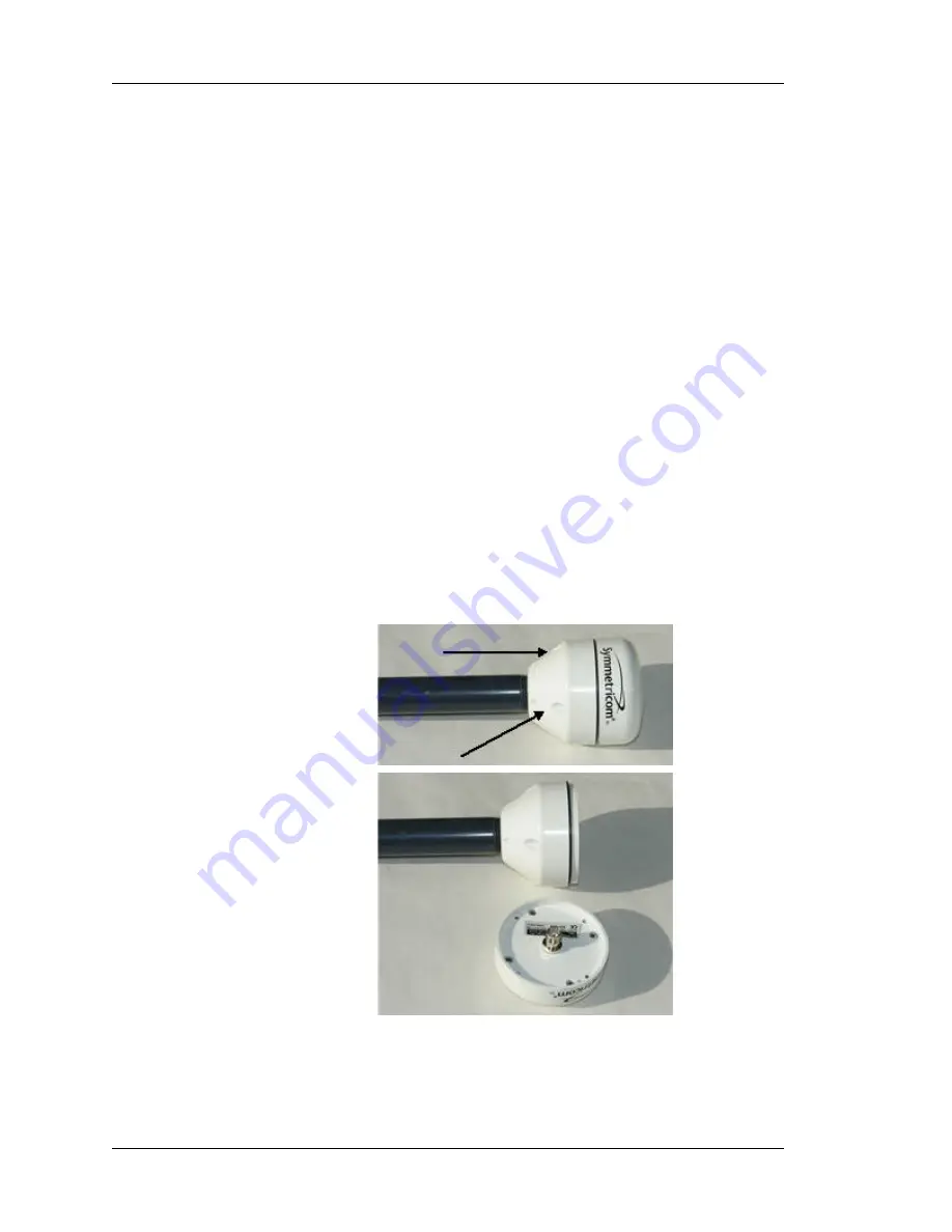
The antenna is housed in completely waterproof packaging designed to with stand the
elements.
When the four
UNC4-40
screws in Figure A are loosened, the antenna module detaches as
shown below, exposing the TNC connector as shown in Figure B.
Figure A
The arrows show two of the four
UNC 4-40 screws
Figure B
Page 22 of 221
.................................
098-00116-000 Rev. A
Summary of Contents for XL-GPS
Page 1: ...XL GPS Time Frequency Receiver User Guide CD Part Number 098 00116 000 Rev A 5 May 2010 ...
Page 14: ......
Page 34: ......
Page 50: ......
Page 196: ......
Page 214: ...IRIG IRIG Standard Format A 098 00116 000 Rev A Page 200 of 221 ...
Page 215: ......
Page 216: ...F World Map of Time Zones 098 00116 000 Rev A Page 202 of 221 ...
Page 219: ......
Page 220: ...I Certificate of Volatility See the following document 098 00116 000 Rev A Page 206 of 221 ...
Page 224: ......
Page 225: ...J Declaration of Conformity See the following document 098 00116 000 Rev A Page 208 of 221 ...


