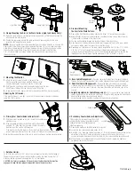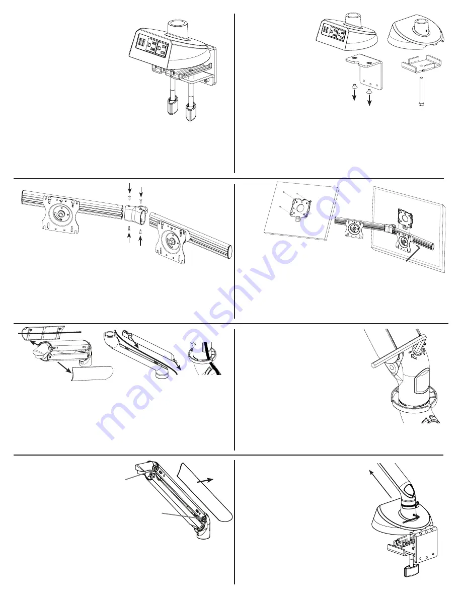
B. Grommet Mounting the
Arm to the Work Surface:
1.
Remove the Arm Clamp Bracket by undoing
the three 1/4” socket head cap screws.
2.
Using a Phillips screw driver, remove the two countersunk screws
which attach the arm clamp bracket to the base of the monitor arm
3.
Lay any monitor cables through the grommet hole on the work surface
4.
Align the base of the monitor arm assembly over the grommet hole on the
work surface, passing any cables under the rear cut-out in the arm base
5.
Depending on the thickness of the work surface insert either the 3/8-16 x 2 1/2” bolt
or 3/8-16 x 3 1/4” bolt through the centre hole in the grommet plate, with the flanges
facing up. Insert the treaded end of the 3/8” bolt through the grommet hole and into
the threaded hole in the arm base & tighten securely with a 9/16” wrench or socket
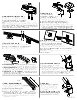
D. Mounting the Monitors:
1.
Attach the quick connect adapter to the rear of the
monitor using the 4mm screws provided. Make sure the
arrow on the adapter is pointing to the top of the screen
2.
With the arrow pointing up, slide the adapter bracket onto the
arm VESA Plate until the bottom tab clicks onto the VESA plate
3.
To remove the monitor, depress the tab to remove from the VESA bracket assembly
Adjusting the tilt tension:
If the monitor drops or is too tight, adjust the tilt tension screw at the side of the head
using the 3/16” Allen key
H. Primary Arm Counterbalance Adjustment:
1.
With the monitors installed on the arm, locate the
counterbalance adjusting screw
2.
If the adjustable arm lowers under the weight of the monitor,
using the 1/4” Allen Key, turn the screw counter clockwise in
the direction of the + arrow until balanced.
If the monitor is difficult to lower or lifts by itself, turn the adjustment screw clockwise
in the direction of the – arrow, until the arm is counterbalanced. Note: Use the
gauge at the rear of the arm to assist in setting up multiple arm installations
E. Base Cable Management -
Pass the cables that extend from the rear of the desk
through the two cable management clips situated between the base and fixed height arm
F. Fixed Arm Cable Management
-
Remove the fixed arm cable cover by pulling sideways
to detach from the arm. Lay the cables into the trough on the cable cover and carefully
re-attach the cover to the arm, then insert the cables into the cable clips at the arm joint
G. Height Adjustable Arm Cable Management
-
Pull to remove the left and right side
cable shrouds and lay the cables into side shroud trough. Carefully replace the side shrouds
ensuring the retaining clips are correctly seated.
Ensure enough slack is provided in cables to provide full arm articulation
C. Attaching the Crossbars to the Hub:
1.
Insert the left hand crossbar into the crossbar hub on the monitor arm
2.
Insert the 6-32 x countersunk screws into the upper and lower mounting holes
3.
Securely tighten the upper and lower screws using a Philips screwdriver
4.
Repeat the above procedure for the right hand crossbar
J. Rotation Limiter:
To limit the arm rotation to 180°, place the arm
straight out towards the front edge of the work
surface, locate the arm rotation limiting screw
on the base & using the 1/8” Allen key tighten
clockwise to engage lock.
Do not over tighten
CAUTION: For total screen loads 20 lbs. or higher,
the Rotation Limiter must be engaged to keep the
load properly supported above the work surface.
I. Secondary Counterbalance Adjustment:
If the monitors do not adjust smoothly or hold position
after the primary adjustment method, further adjustment
is available using the following procedure
1.
Remove the right hand height adjustable arm shroud
2.
Locate the two countersunk screw heads A & B
3.
Using the 3/16” Allen Key, tighten the screws in 1/2 turn increments to fine tune the
friction adjustment of the arm. Clockwise rotation will increase the friction on the joint and
counterclockwise will decrease the friction. Both A & B screws should be adjusted equally
4.
When the arm is counterbalanced to support the monitor load, replace the right hand
height adjustable arm side shroud
A. Clamp Mounting the Arm to the Work Surface:
1.
Open the clamp pad/s by unscrewing the clamping knob/s,
so that the clamp assembly will slide onto the work surface
2.
Position the arm assembly onto the work surface and securely
clamp to the work surface by tightening the clamp knob/s
NOTE:
For panel systems where the assembled clamp cannot be attached as an assembly.
Remove the Lower Clamp Assembly by removing the three 1/4” socket head cap screws. Slide
the arm clamp bracket in the space between the rear of the desk and panel system, then attach
the Lower Clamp Assembly to the arm clamp bracket using the three 1/4 - 20 socket head cap
screws. Tighten the clamp knob/s to securely clamp to the work surface.
Screw A
Screw B
7762180 Rev_A
Height
Adjustable Arm
Fixed arm
Arm Clamp
Bracket

