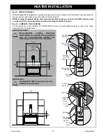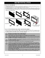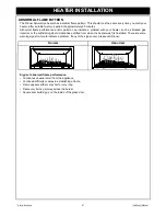
Rinnai Australia
27
Installation Manual
HEATER LOCATION
LOCATION
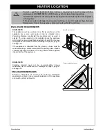
• When positioning the heater, variables governing the location are Flueing and Warm Air Distribution.
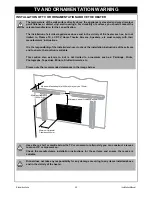
• This heater must not be installed where curtains or other combustible materials could come into contact with
it. In some cases curtains may need restraining. Refer to page 7 for additional safety consideration.
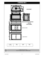
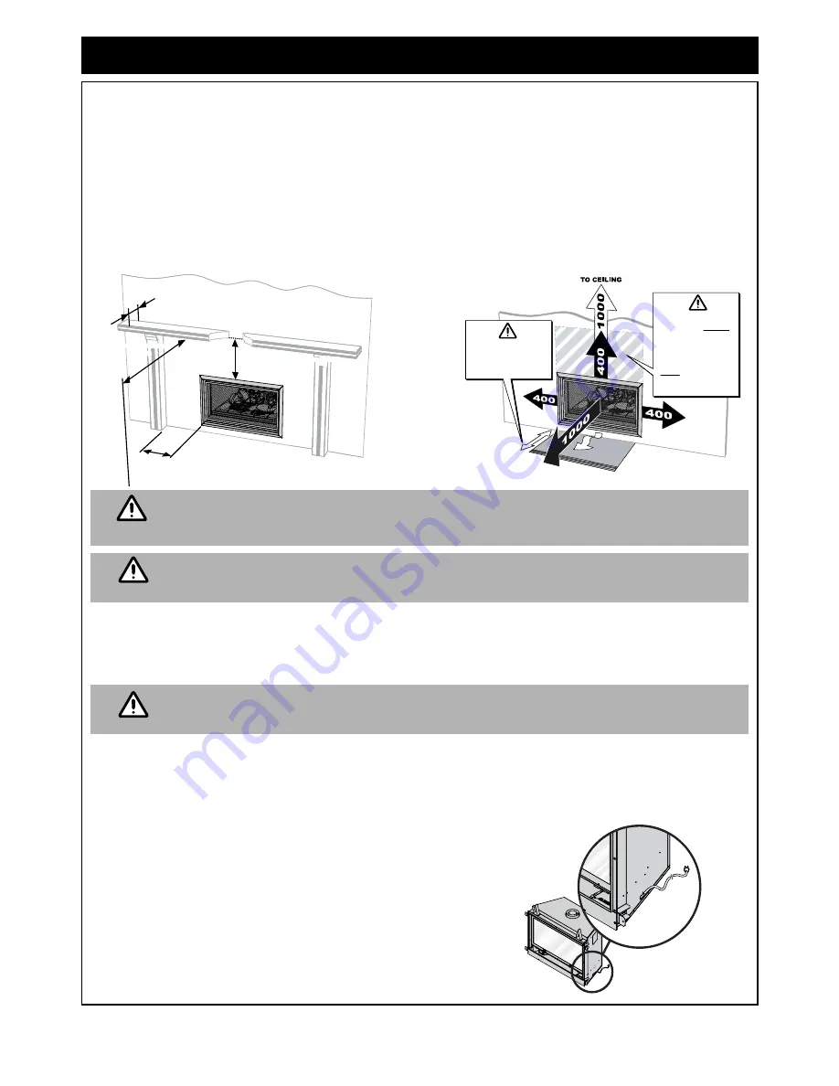
• Mantles and surrounds can be added to compliment the design provided that they conform to the clearances
shown in the drawings below.
• The minimum clearance from the mesh dress guard edge is 400 mm. The depth of the mantle/surrounds at
the minimum clearance may not exceed 150 mm.
• An additional 100 mm of clearance is required for every extra 50 mm of mantle depth, i.e. for a 200 mm deep
mantle the clearance is 500 mm (as shown below).
Clearances are the same for Bevelled and Square Fascia’s.
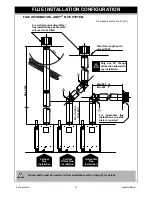
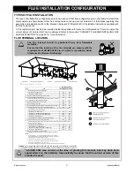
For all installations. Only as specified Abey
®
Co-Axial Flue components MUST be used.
The Rinnai Symmetry
®
MUST NOT be flued into ‘natural draft’ flue system or terminate into
a chimney.
GAS SUPPLY
The gas supply terminates inside the heater at the front lower left hand side of the appliance.
Locate the gas supply pipe to suit position as per the heater gas inlet. Refer to “CONNECT THE APPLIANCE TO
CONSUMER GAS PIPING” on page 36 for appliance gas inlet location.
Gas pipe sizing must consider the gas input to this appliance as well as all other gas
appliances in the premises. The gas meter and regulator must be specified for the total gas
rate. Suitable sizing chart such as the one in AS/NZS 5601 should be used.
PURGING THE GAS SUPPLY
• All foreign materials such as filings must be purged from the gas supply, before connecting to the appliance
as they may cause the gas control valve to malfunction.
ELECTRICAL SUPPLY
• This heater is supplied with a power cord (length 1500 mm)
and three pin plug. The power cord passes through the right
hand side panel as shown. Rinnai recommend the heater be
plugged into a 240V, 10A earthed power point. The power
point must not be above the heater.
A suitable means of electric isolation must be provided which
is adjacent to the appliance and accessible with the appliance
installed, in accordance with AS/NZS 5601.
• The appliance can be direct wired if the power supply is to be
concealed. An isolator switch MUST be used in accordance
with AS/NZS 5601 & AS/NZS 3000.
Minimum Horizontal
Clearance 400mm
Maximum Mantle depth (at 400mm) may only be 150mm.
Minimum Vertical Clearance 400mm
Minimum Clearance
1000mm
On heat sensitive
surfaces provide
protective matting
to at least 750mm
Non-combustible
cladding MUST
be provided for
RDV3610ETR
installations.
NOT required on
RDV3611ETR
installations.
NOTE
WARNING
WARNING


