9 | Voyager
ASSEMBLY
INSTRUCTIONS
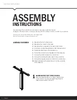
ASSEMBLE THE FOOT TO THE COLUMN
Assemble using the M10x1.5 x 50mm length screws
(2 per column). The maximum tightening torque for
these screws is 48Nm. (35 lbs-ft).
ASSEMBLY OVERVIEW
1.
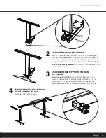
Assemble the foot to the column
2.
Assemble the column to the beam
3.
Assemble the top support to the beam and column
4.
Feed motor cables through beam or HAT channel cutout
5.
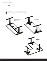
Fasten the table frame onto the table top
6.
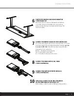
Fasten the control box and handswitch to the table top
7.
Connect the motor cables to the control box
8.
Connect the handswitch (HS) cable to the control box
9.
Connect the supplied power cord (AC) to the control box
10.
Attach all cables to the table frame or on the underside
of the table top
ASSEMBLY INSTRUCTIONS
The assembly of the table frame to be made in accordance with this manual.
Changes to the table frame or improper use may affect the safety, function, and life of your product.
This manual is for all sit-stand tables from the Voyager series.
Due to different models or types, pictures may vary.
1


