background image

To report any issues with this product, please contact our customer service department at (888) 552-5699.

For more information, visit www.symmetryoffice.com

VOYAGER TROUBLESHOOTING

16

16

16

CODE   

SOURCE

SOLUTION

H0T 

The control box monitors the duty cycle 

(time-controlled) and its maximum 

temperature. A value has been exceeded.

Wait until the “H0T” display goes out - the table is working properly 

again

E00

M1 – Internal fault

Unplug and contact customer service.

E01

M2 – Internal fault

E02

M3 – Internal fault

E12 

M1 – Defect

Unplug. Correct the external short circuit and/or verify the cable to 

the drives. Plug cables into the control box and re-initialize the table 

(see page 12.)

E13

M2 – Defect

E14

M3 – Defect

E24

M1 – Overcurrent

Collision — Resolve if necessary.

E25

M2 – Overcurrent

Maximum load exceeded — Remove excess load from table.

E26

M3 – Overcurrent

If the problem still exists, please contact customer service.

E36

M1 – Not connected

Motor not connected. Check cable/connector to the drive.  

Reset the table (see page 12).

E37

M2 – Not connected

E38

M3 – Not connected

E48

Overcurrent drive 1

Collision — Resolve if necessary.

E49

Overcurrent drive 2

Maximum load exceeded — Remove excess load from table.

E55

Drive 1 – Synchronization is lost

If necessary, reduce the load on the table.

E55

Drive 1 – Synchronization is lost

Reset the table (see page 12).

E60

Collision identified

Optional ISP function — Remove source.

E61

Drive replaced

The connection to the drive is interrupted or a new drive is 

connected. Reset the table (see page 12).

E67

High voltage

Unplug the power cord and contage customer service. High voltage 

driver in control unit failed.

E81

Internal error

Make a manual reset (see page 12). Unplug the power cord then 

plug it in again after a few seconds. If this error occurs frequently, 

unplug the power cord and contact customer service

E93

Connection error in the cascaded network

Check all the cable connections and try to reset the motors. If you 

cannot reset the motors, disconnect all the control units from the 

power supply. Wait for at least 5 seconds and then reconnect all the 

control units to the power supply. Try again to reset the motors. If 

you still cannot reset the motors, please contact customer service.

UNDERSTANDING ERROR CODES

If it is not possible to resolve an error as described, disconnect the power cord, wait a few minutes 

and reset the table again. If the error still occurs, remove the table from the power source and contact 

customer service. 

Summary of Contents for Voyager

Page 1: ...L VOYAGER ASSEMBLY INSTRUCTIONS Reach new heights with the Voyager 2 leg sit stand table Designed and built to be configurable for spaces of any shape and size get the do it all desk that works with a multitude of convenient workspace options ...

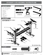
Page 2: ... TABLE TOPS UNDER 72 Cordless Drill Driver Do not over tighten screws Torx L Key T40 Size Hex L Key 6 mm Size 2 Phillips Head Screwdriver or Bit Top Support Column Foot M10 1 5 30 mm Screws M8 1 25 12 mm Screw Foam Motor Housing 10 Screws Power Cord Control Controller Do not remove foam 10 Screw M10 1 5 30 mm Screw M8 1 25 12 mm Screw M8 1 25 12mm Screws 8 M10 1 5 30 mm Screws 4 10 Screws 22 Colum...

Page 3: ...25 12 mm Screws Foam HAT Channel Motor Housing 10 Screws 10 Screws Power Cord Control Controller Do not remove foam 2 LEG VOYAGER WITH HAT CHANNEL FOR 72 TABLE TOPS Cordless Drill Driver Do not over tighten screws Torx L Key T40 Size Hex L Key 6 mm Size 2 Phillips Head Screwdriver or Bit 10 Screw M10 1 5 30 mm Screw M8 1 25 12 mm Screw M8 1 25 12mm Screws 8 M10 1 5 30 mm Screws 4 10 Screws 30 Colu...

Page 4: ... www symmetryoffice com VOYAGER 2 LEG ASSEMBLY INSTRUCTIONS STEPS 1 4 1 Check to make sure the top supports are 13 8 from the edge of the table top and align the support with the pilot holes 2 Attach both top supports to the underside of the table top using a 2 Phillips head screwdriver or bit and the 10 screws 8 per top support ...

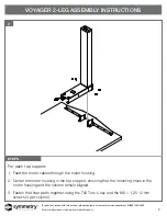
Page 5: ...om VOYAGER 2 LEG ASSEMBLY INSTRUCTIONS STEPS 2 5 For each top support 1 Feed the motor cables through the motor housing 2 Center the motor housing in the top support ensuring that the mounting holes in the motor housing and the column remain aligned 3 Fasten the three parts together using the T40 Torx L key and the M8 1 25 12 mm screws 4 per column ...

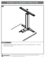
Page 6: ...ntact our customer service department at 888 552 5699 For more information visit www symmetryoffice com VOYAGER 2 LEG ASSEMBLY INSTRUCTIONS STEPS 3 6 1 Attach the feet to the columns using the 6 mm hex L key and the M10 1 5 30 mm screws 2 per column ...

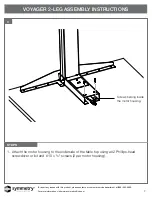
Page 7: ...at 888 552 5699 For more information visit www symmetryoffice com VOYAGER 2 LEG ASSEMBLY INSTRUCTIONS STEPS 4 7 1 Attach the motor housing to the underside of the table top using a 2 Phillips head screwdriver or bit and 10 screws 2 per motor housing Screws belong inside the motor housing ...

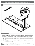
Page 8: ... STEPS 5 5 8 Complete this step only if using a HAT channel HAT channels are required for tables with a length of 72 or greater If no HAT channel is being used proceed to step 6 1 Feed the motor cables through the HAT channel before attaching the HAT channel to the table top 2 Attach the HAT channel to underside of the table top using a 2 Phillips head screwdriver or bit and 10 screws 8 ...

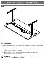
Page 9: ...RUCTIONS STEPS 5 6 9 Making sure that the control box and controller are fastened in a location where all the cables will connect without tension 1 Fasten the control box to the underside of the table top using a 2 Phillips head screwdriver or bit and 10 screws 2 2 Fasten the controller to the underside of the table top using a 2 Phillips head screwdriver or bit and 10 screws 2 ...

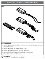
Page 10: ... LEG ASSEMBLY INSTRUCTIONS STEPS 5 7 10 1 Connect the motor cables M1 M2 to the control box The motor cable plug connection should click into place 2 Connect the controller HS cable to the control box 3 Connect the supplied power cord AC to the control box 4 Attach all cables to the table top to avoid damage during operation Never attach cables or cords to legs ...

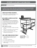
Page 11: ... entire range of motion Before raising or lowering Check the surroundings on all sides of the table are clear Make sure corded objects will not be pulled off the table or cause other objects to fall Make sure the table power cord moves freely as desk moves up and down USE CARE WHEN MOVING TABLE Clear all objects and equipment from the table before rolling to reduce the risk of tipping over Do not ...

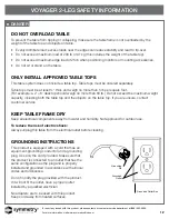
Page 12: ... 5 lb per square foot For example a 2 6 desktop should weigh no more than 60 lb Do not exceed the maximum weight capacity including both the table top and the objects on the table top If you are unsure contact customer service KEEP TABLE FRAME DRY Keep all electrical components away from water and humidity Not approved for outdoor use To reduce the risk of electric shock Always unplug this table f...

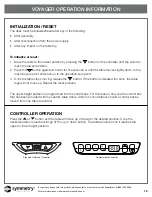
Page 13: ...l the table moves slightly down to the machine zero point and back up to the operation zero point 3 Once the table stops moving release the button If the button is released too soon the table legs will not move up Repeat the reset process The upper height position is programmed into the control box For this reason only use the control box that has been provided with the specific table frame Under ...

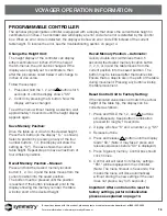
Page 14: ...Repeat steps to save a maximum of four different positions Recall Memory Position Manual Press and hold the desired memory location button 1 2 3 or 4 and the table moves from the current position into the saved position The button must be pressed until the position is reached If the button is released prior to the display showing the memory number the table will stop short of the desired height Re...

Page 15: ...e connection on the control box No connection or a loose connection to the drives Verify the plug connections of the motor cable to the control box No connection or a loose connection to the controller Verify the plug connections of the motor cable to the control box Maximum lifting capacity is exceeded Reduce the weight or load on the desktop Maximum time limit is exceeded Control is activated au...

Page 16: ...ve 2 Maximum load exceeded Remove excess load from table E55 Drive 1 Synchronization is lost If necessary reduce the load on the table E55 Drive 1 Synchronization is lost Reset the table see page 12 E60 Collision identified Optional ISP function Remove source E61 Drive replaced The connection to the drive is interrupted or a new drive is connected Reset the table see page 12 E67 High voltage Unplu...

Page 17: ...lift capacity 200 lb 90 kg 890 N Adjustable range 18 9 Maximum input current 6 5 A Maximum duty cycle 10 2 minutes on 18 minutes off TECHNICAL DATA STANDARDS AND CERTIFICATIONS The drive system is tested according to the following standards UL 962 Issued 2014 11 07 Ed 4 Household and Commercial Furnishings CSA C22 2 68 Issued 2009 09 01 Ed 7 R2014 Motor Operated Appliances Household and Commercial...

Reviews: