Pulse Width Measurement Mode
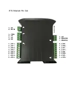
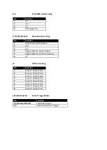
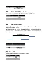
The auxiliary pulse width measurement interface connector allows for the integration, and daisy
chaining, of sensors which require a low 5V voltage power supply and/or trigger pulse in order to
initiate conversion/pulse generation. The width/length of the received pulse is then measured and
stored in the respective Modbus register.
The functionality here has been specifically designed with Maxbotix ultrasonic range sensors in
mind, although the interface is generic and can be used with any sensor providing a varying pulse
width.
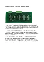
In addition the RTU module can optionally be paired with a breakout board specifically designed for
daisy chaining up to 8 Maxbotix ultrasonic sensors; this gives maximum reliability and prevents
“cross talk” between sensors if placed in close proximity.
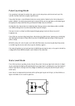
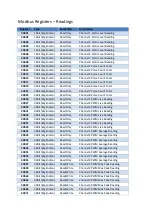
Pulse width readings also have special averaging and peek max/min recorders for alarm sensing
PWM “Olympic Average” Reading
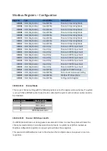
This gives the per-channel rolling average over 6 or 10 readings, here the maximum and minimum
readings from each channel are discarded from the data-set and the average is then calculated over
the remaining 4 or 8 readings. This method is used to assist with positively eliminating any
substantially outlying readings which may have occurred during the period, for example if the signal
source is fluctuating or the sensor has produced a glitched/bad read.
PWM Max/Min Peek Reading Indicators
These values are set and tested against at each sensor read, if the current reading exceeds the
Max/Min threshold then the Max/Min value is overwritten with the current reading and the new
updated value is then used on subsequent reads. This value can also be set via a Modbus write
giving allowing the setting to act as a threshold for an alarm level
Note that all PWM readings/thresholds are volatile and will not be retained over a power on/off/on
cycle


