
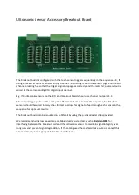
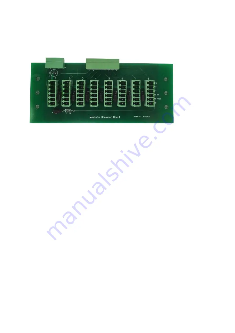
Ultrasonic Sensor Accessory Breakout Board
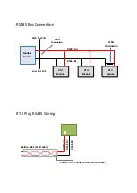
The breakout board is configured such that each sensor triggers sequentially in the sequence 1-8, if
using a smaller amount of sensors strictly use the 1-8 ordering for both the sensor plugs and the RTU
channel ordering the so that the trigger signal propagates correctly and the matching pulse output is
wired to the corresponding RTU digital input channel.
E.g. If 4 ultrasonic sensors are the RTU and breakout board should use channel numbers 1-4
The sensor trigger pulse will be sent by the RTU module once to start the sequence, the Maxbotix
sensors should be wired in daisy chain format to allow this signal to feed through each sensor in the
sequence for optimum results.
The breakout board can be mounted on a DIN rail by using the plastic adapter clips provided.
We recommend using low capacitance cabling, ideally twisted pair, such as
Belden 9931
for
interfacing between the breakout card and the ultrasonic sensors to maintain signal integrity over
long runs and prevent signal degradation. If the cabling used has a shield make sure to connect this
at one end only to an appropriate 0V/Ground reference.


