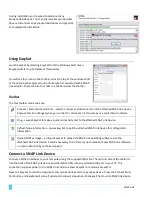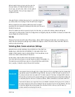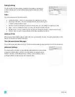
Set up a unit as a
multipoint master
While in multipoint mode, again press the MODE button 4 times in rapid succession. LED A
will then blink slowly, alternating between green and amber, indicating the unit is the
master in a multipoint network. Any slave units on the same channel and with the same
network ID, which were previously set to multipoint mode, will then begin pairing with the
master. If LE
D A should begin alternating between red and amber, that indicates another
master is already on the same channel and with the same network ID.
Back out of
multipoint mode
when previously
set up as a master
If the unit was previously set up as a master, press and hold the MODE button (for at least
5 seconds) until LED A rapidly flashes. The unit is no longer a master, but is still in
multipoint mode, and is now looking for a master with which to pair.
Back out of
multipoint mode
altogether
If the unit was previously set up as a master, first back out by following the procedure
above. Then, press and hold the MODE button again (for at least 5 seconds) until LED A
glows steadily. Release and the unit is now back in broadcast state. It can now be set up in
point-to-
point mode or in multipoint mode.
Pin Outs
RS-232 (DB9F) Pin Outs
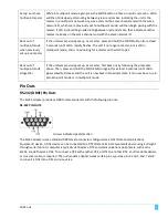
The SL232 adapter provides a DB9 female connector with the following pin outs:
RS-232 PIN OUTS
Arrows indicate signal direction
The SL232 adapter uses a standard DB9 female connector configured as a DCE (Data Communications
Equipment) device. A DCE device can be connected to a DTE (Data Terminal Equipment) device using a straight
through serial cable. A computer is typically defined as a DTE and communications peri
pherals, such as the
SL232, are defined as a DCE. To connect a DCE with another DCE, or DTE to another DTE, a null modem adapter,
or crossover cable, is required. The null modem adapter swaps certain pins, typically pins 2 and 3, and 7 and 8,
to convert a
DCE into a DTE and vice
-versa.
SNAP Link
5
Summary of Contents for SNAP Link
Page 4: ......

