IZ2M/IZ2MH Stimulators
Fast Facts
LED Indicators
LEDs
Status
Blue* Yellow Red
Power on (Safe Mode) blink off
off
Ready to ARM
solid solid
off
Arming
solid solid
blink
Ready to Stim (Armed) solid solid
solid
Safety Fault
blink off
off
Com Failure
solid blink
off
Safety Fault/Com Error blink off
off
*When actively stimulating (no faults) the Blue LED also
blinks to indicate temperature deviation from optimal.
Power Status Lights
Running from mains
green
Running from battery
red
Battery Level Lights
Power Level
# of LED’s Lit
Fully charged
4
Not fully charged
3-2
Critically low, charge immediately
1
Stim Lights
Labeled by channel number, each LED indicates
the voltage at the corresponding electrode site.
Channel output is > +/- 150 mV
green
Channel output is > +/- 10 V (clipping) red
This fast facts sheet provides basic reference
information for the IZ2M/IZ2MH Stimulator and
related devices. See the System 3 Manual for more
detailed information.
The stimulator is available with 32 or 64 channels
and standard (M) or high current (MH) versions.
Output Voltage
+/- 12 V
IZ2M Output Current +/- 300 µA
up to 40 kOhm load
IZ2MH Output C/- 3 mA
up to 4 kOhm load
Arming Sequence.
Before the stimulator can be armed the RZ
processor must be connected to the stimulator and the battery
should be fully charged. If the stimulation circuit is loaded and
running, it MUST NOT be actively sending stimulus signals on any
channels.
The instructions below provide step-by-step sequence and more
detail about each stage of device operation.
Step one. Boot—Press the battery power button to power on.
The
blue LED on the mains power switch blinks until the device comes up to
optimal temperature.
See the LED Indicator table to the right for safety fault or communication
failure LED light patterns. When all safety checks have passed, both the
blue (Power) and yellow (Ready) LEDs will be lit (no flashing), indicating the
device is ready to arm.
Step two. ARM—Hold down the Start/Stop button for 3 seconds.
When the red LED flashes the Start/Stop button may be released and the
red (Armed) LED will remain lit. See the LED Indicator table to the right for
fault LED light patterns.
Step three. Stimulate—Send stimulation (up to 10 channels) from
the RZ processor.
Once the device is armed, by default all channels are
open and open/close state can be controlled from run-time applications.
The stimulator will deliver stimulation to the subject whenever stimulation
signals are received from the RZ processor.
The stimulator faults and returns to safe mode (all channels open/no
curent output possible) if either of the below occurs:
•
Stimulation is attempted on more than 10 channels.
•
More than 100 mA total output is detected by the compliance board.
Note: It’s not possible to reach 100 mA under normal conditions.
Step four. STOP—Press Start/Stop button.
Press the Start/Stop
button at any time to stop stimulation immediately and revert to safe
mode.
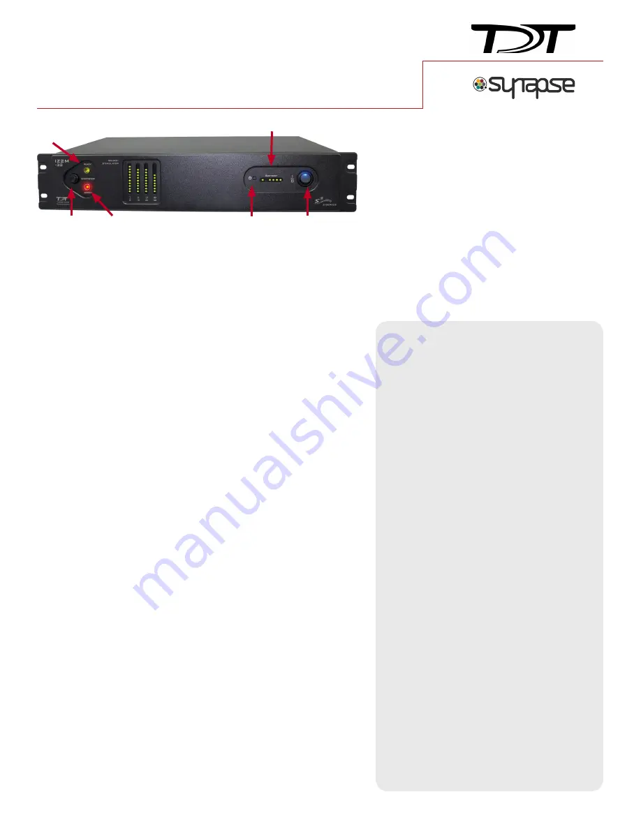
Ready
Armed
Start/Stop
Mains Power
Battery Power
Battery/Power LEDs
WITH


