background image


pg. 7 


Any repair or maintenance work must be conducted by a qualified engineer or recognized service agent. 

 
WARNING 


The Synergy Air Bionic Cycle is user powered. The user controls the speed of the movement.  

There is no emergency stop function in the Synergy Air Bionic Cycle.  

Every user must become familiar with the mechanism and functions before using the Synergy Air Bionic Cycle. 

Ensure entry to the Synergy Air Bionic Cycle is via the rear, gripping the handles when embarking or disembarking 
the Synergy Air Bionic Cycle. 

The Synergy Air Bionic Cycle must be installed vertically on a hard, level surface. 

Keep hands away from all moving surfaces and components. 

Do  not  allow  a  towel  or  clothing  to  become  caught  in  the  moving  surface  of  the  Synergy  Air  Bionic  Cycle. 
Shoelaces must be enclosed and short enough not to touch the foot pedals. Do not use high heels, or shoes with 
leather soles. 

Always use the handles when embarking or disembarking the Synergy Air Bionic Cycle. 

Examine the Synergy Air Bionic Cycle regularly for safe operation. Repair any problem immediately it is identified. 
Implement a regular maintenance plan for the Synergy Power Tower at minimum quarterly intervals. 

Summary of Contents for SYN-KABC

Page 1: ...Synergy Air Bionic Cycle SYN KABC User Manual Version 1 2...

Page 2: ...Air Bionic Cycle ASSEMBLY INSTRUCTIONS 9 Technical Specifications 14 SYN KABC INSTRUCTIONS FOR USE 16 Installation 16 Handlebar and seat adjustment 16 Adjusting the Seat height plus forward backward p...

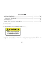
Page 3: ...Duty of Care Acknowledgement 20 BEFORE YOU START The following safety sign is affixed to the Synergy Air Bionic Cycle Please read the following safety instructions precautions and information before...

Page 4: ...ce with these instructions Keep your hands away from all moving parts Never turn the pedal crank arms by hand Do not remove your feet from the pedals or your hands from the handlebar while they are in...

Page 5: ...d tear on a regular basis Components that are worn excessively or inoperable should be replaced immediately or the bike should be put out of use until it is repaired DANGER Do not wet the surface of t...

Page 6: ...st be obtained from a health professional for any of the following health conditions of the user pregnancy heart disease high blood pressure diabetes chronic respiratory disease high cholesterol cigar...

Page 7: ...g the Synergy Air Bionic Cycle The Synergy Air Bionic Cycle must be installed vertically on a hard level surface Keep hands away from all moving surfaces and components Do not allow a towel or clothin...

Page 8: ...pg 8...

Page 9: ...ynergy Air Bionic Cycle ASSEMBLY INSTRUCTIONS The model SYN KABC is designed to be used as an individual or group cycle in fitness studios and health clubs In your cardboard box you will find the foll...

Page 10: ...e fixing plate 18 Console Cable 19 Front stem 20 Screw M8 x 2 21 Washer x 2 22 Spring washer x 2 23 Bottle cage 24 Screw M5 x 2 30 Nylon nut M8 x 4 45L Left crank 45R Right crank 46L Left pedal 46R Ri...

Page 11: ...ssemble the front stabiliser 6 to the frame by using the bolt 5 and washer 4 Align and assemble the rear stabiliser 2 by using the bolt 3 washer 4 Pull the cable 18 through the front stem 19 before se...

Page 12: ...mp 96A Slide right dual swing bar 47R onto right side followed by nylon nut 53 dust cover 54 and finally screw on the axle peg 62 Attach the dual swing bar 47R to linkage arm using washer 58 nylon nut...

Page 13: ...followed by nylon nut 53 dust cover 54 and finally screw on the axle peg 62 Attach the dual swing bar 47R to linkage arm using washer 58 nylon nut 30 and pivots cap 59 Attach the right peddle to the r...

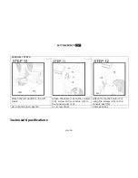
Page 14: ...the left crank Attach the cable 18 to the console 16 Screw on the console 16 to the console post 19 Attach the bottle holder 23 using the screws 24 to the console post 19 Use a 15mm open wrench screw...

Page 15: ...nic Cycle is a non motorized product The Synergy Air Bionic Cycle uses air turbine to provide resistance Dimensions 143cm H x 60cmW x 120cm L 56 x 23 x 47 No Description QTY 1 Left handle arm 1 2 Righ...

Page 16: ...be carried out by suitably qualified personnel Handlebar and seat adjustment It is important that the seat is set at the correct height for your body Ask your instructor for assistance Adjusting the S...

Page 17: ...t your foot as far forward as you can into the toe clip and then pull the strap tight Maintenance Like any other mechanical cycling device the SYN KABC should be regularly maintained Daily Maintenance...

Page 18: ...Note Do not apply Lanoline to handles and or Foot plates Clean the console with a soft cloth Check all bearings pedals handlebar seat adjustment knobs are still secure and functioning optimally If re...

Page 19: ...pg 19 Exploded diagram...

Page 20: ...rning labels on each machine and that reference is made to the exercise Instructional Placards fitted to Strength pin loaded machines 2 It is understood that many of the machines racks benches can be...

Reviews: