background image

Section III 

Operation

006-0006715  10/31/18 


Rev J 

26 of 44 

MPS-MPPS-4000 Guide 

www.synqor.com

Programming The Output:  MPPS Only

For the MPPS, the output voltage and output current can be programmed using the RS‑232 

interface or using the web page interface.  The MPPS cannot be programmed using the SNMP 

interface.

Programming the Output From the Web Interface

• Ensure the web interface is configured properly.  See the Ethernet/SNMP user guide for 

details: 

 http://www.synqor.com/mps/documents/MPS_Ethernet_SNMP_UG.pdf

• Navigate to the “control” tab.  The default address is http://169.254.1.1/control.htm
• In the “Configuration” section, enter the desired output voltage in mV click UPDATE.  For 

example “30000” corresponds to 30.000V output.

• In the “Configuration” section, enter the desired output current in amps click UPDATE.  For 

example, “50” corresponds to 50A.  


Summary of Contents for MPPS-4000 Series

Page 1: ...MPPS 4000 1U 1 888 567 9596 USA only SynQor Headquarters 155 Swanson Road Boxborough MA 01719 1316 USA www synqor com Made in USA Military Field Grade Power Supply Operator s Guide MPS 4000 Series MPPS 4000 Series ...

Page 2: ...pology MPPS 8 Part Numbering Scheme and Options MPS 9 Part Numbering Scheme and Options MPPS 10 Product Specifications 11 Technical Specifications MPS 12 Technical Specifications MPPS 13 Programmable Features MPPS 13 Technical Specifications MPS MPPS 14 1U Mechanical Diagram 15 Efficiency MPS 16 Total Output Power MPS 17 Efficiency MPPS 18 Total Output Power MPPS 19 Temperature Derating 20 MPS Dro...

Page 3: ...t 33 Section IV Control Interface Details Control Cable Connections 34 Internal User I O Circuits 35 Remote On Off Switch Connections 35 Digital Input Output Control Signals 36 RS232 Serial Interface 36 Ethernet Interface 37 Synchronized Operation of Multiple Units MPS 38 Turn On Turn Off Restart Control 38 Fault Synchronization Control 38 Parallel Operation of Multiple Units MPPS 39 Turn On Turn ...

Page 4: ...ower before disconnecting it from the MPS MPPS If the AC input cable is connected to the source of AC power and not connected to the MPS MPPS do not contact the exposed terminals of the AC input cable Do not assume that the source of AC power is not present ConnectionsbetweentheACinputcableandthesourceofACpowershouldnotbeaccessible For the MPPS DC OUTPUT cable and connector The DC output terminals...

Page 5: ...ned in a sealed chamber It is capable of withstanding harsh levels of mechanical acceleration shock and vibration temperature and pressure variations and exposure to water salt sand and dust within the levels specified in the data sheet THESE LEVELS SHOULD NOT BE EXCEEDED Do not obstruct the air intake in the front of the MPS MPPS or the fan exhausts in the rear panel of the MPS MPPS while the MPS...

Page 6: ... to set the output voltage and output current TheelectroniccircuitrywithintheMPS 4000andMPPS 4000Seriesproductsisdesigned qualified and screened according to SynQor s MIL COTS Standards It complies with the requirements of MIL STD 704F MIL STD 1399 300B MIL STD 1275D and MIL STD 461F as well as IEC EN61000 specifications for world wide commercial utility applications The MPS 4000 and MPPS 4000 Ser...

Page 7: ...nces EMI filters are present at all external inputs and outputs AC INPUT MAIN DC OUTPUT AC to DC w PFC and ISOLATION OUTPUT FILTERING OUTPUT CAPACITOR INTERFACE CONTROL Power flows from the AC INPUT through an AC DC converter that has Power Factor Correction PFC and high frequency safety isolation The DC outputs at various voltage and power levels are available The DC can deliver up to 4000 W 5250...

Page 8: ...lly Controlled Vset Imax OUTPUT FILTERING Ideal Diode INTERFACE CONTROL Power flows from the AC INPUT through an AC DC converter that has Power Factor Correction PFC and high frequency safety isolation The DC outputs at various voltage and power levels are available The DC output voltage and maximum output current can be programmed by the user The DC output can deliver up to 4000W Bulk energy stor...

Page 9: ...sentative Part Numbering Example MPS 4000 1U 3W2ES00 E00 The MPS 4000 Series of products provide up to 4000 W 5250W transient of total output power Optionsthatcanbespecifiedaccordingtothepartnumberingschemeshowninthetableinclude The allowable frequency of the AC INPUT can be in the 47 800 Hz range The nominal output voltage of the MPS 4000 Series can be 28 V 30 V or 48 V The DC OUTPUT is semi regu...

Page 10: ...0 W of fully regulated DC output power Various options can be specified according to the part numbering scheme shown in the table The allowable frequency of the AC INPUT can be in the 47 800 Hz range The default output voltage of the MPPS 4000 Series can be 28 V 48 V or 72 V These models are capable of 150A 120A and 78A maximum current respectively The DC OUTPUT is fully regulated When placed in p...

Page 11: ...0 1U Series of products Data sheets showing these specifications and other information can be found at the web site http www synqor com MPS MPS 4000 1U Unit or MPPS 4000 1U Unit Front Panel On Off Switch DC Output Ethernet Port Fan Exhaust User I O CONFIG Port Ground Stud 1 4 20 AC Input Fan Exhaust Circuit Breaker Status Indication Panel 1 73 1U 17 00 Air intake MPS 4000 1U Unit or MPPS 4000 1U U...

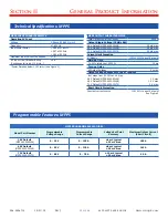
Page 12: ...s 4000 W 15 s Transient 5250 W Nominal DC Output Voltage at No Load 28 Vout 29 7 V 30 Vout 32 2 V 48 Vout 51 5 V DC Output Voltage over Line Load Temperature Semi regulated see Figures 3 5 28 Vout 30 3 27 6 V 30 Vout 32 8 29 9 V 48 Vout 52 5 47 9 V Maximum Output Capacitance 28 Vout 255 mF 30 Vout 222 mF 48 Vout 86 8 mF Output Ripple Voltage 20MHz BW All Output Voltages 0 5 peak to peak of rated V...

Page 13: ...2 2 V max Short Circuit Protection Constant current source 110 120 Current Set point See Figure 4 MPPS INPUT CHARACTERISTICS Operating AC Input Voltage 3 Phase 80 265 VrmsL L Frequency 47 800 Hz Input Power Factor 0 98 at 47 65Hz 0 97 at 400Hz 0 92 at 800Hz Maximum Input Current Continuous 27 A AC Input Circuit Breaker Rating 30 A Continuous full load 110 VrmsL L Power Derating below 110 VrmsL L s...

Page 14: ...rocedure 1 Shipboard Equipment RELIABILITY CHARACTERISTICS MIL HDBK 217F MTBF 240 kHrs MIL 217F Ground Benign Ta 25 C ELECTROMAGNETIC CAPABILITY MIL STD 461F CE101 30 Hz 10 kHz CE102 10 kHz 10 MHz CS101 30 Hz 150 kHz CS106 10 kHz 40 GHz CS114 10 kHz 200 MHz CS116 10 kHz 100 MHz RE101 30 Hz 100 kHz RE102 10 kHz 18 GHz RS101 30 Hz 100 kHz RS103 2 MHz 40 GHz Technical Specifications MPS MPPS MECHANIC...

Page 15: ... 10 31 18 Rev J 15 of 44 MPS MPPS 4000 Guide www synqor com 1U Mechanical Diagram MPS MADE IN USA 17 00 431 8 20 42 518 6 1 49 37 8 19 34 491 1 750 19 05 16 000 406 4 750 19 05 750 19 05 860 21 84 313 7 95 TYP UNIT MOUNTING HOLES 8 32 250 x24 1 73 43 9 ...

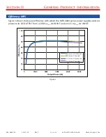
Page 16: ...s the typical efficiency with which the MPS 4000 series power supplies delivers power to its DC OUTPUT from a 208 VrmsL L AC INPUT and an 115 VrmsL L AC INPUT 65 70 75 80 85 90 95 100 0 1000 2000 3000 4000 5000 Efficiency Output Power W 208 Vrms L L Continuous 208 Vrms L L Transient 115 Vrms L L Continuous 115 Vrms L L Transient Figure 1 ...

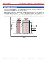
Page 17: ...range 140 VrmsL L 160 VrmsL L the MPS will not be able to deliver its full rated output power in both the steady state and transient situations Fig 2 indicates the total steady state and transient output power that the MPS can deliver under these conditions 0 1000 2000 3000 4000 5000 6000 60 80 100 120 140 160 180 200 220 240 260 280 Output Power Watts Input AC Voltage VrmsL L Transient 2s Continu...

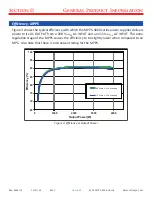
Page 18: ...es delivers power to its DC OUTPUT from a 208 VrmsL L AC INPUT and an 115 VrmsL L AC INPUT The extra regulation stage of the MPPS causes the efficiency to be slightly lower when compared to an MPS Also note that there is no transient rating for the MPPS 65 70 75 80 85 90 95 100 0 1000 2000 3000 4000 Efficiency Output Power W 208 Vrms L L Continuous 115 Vrms L L Continuous Figure 3 Efficiency vs Ou...

Page 19: ...full rated output power in both the steady state and transient situations Figure 4 indicates the total steady state and transient output power that the MPPS can deliver under these conditions Unlike the MPS the MPPS does not have a transient power rating Exceeding 4000W under any condition will cause the output voltage to fold back 0 1000 2000 3000 4000 5000 60 80 100 120 140 160 180 200 220 240 2...

Page 20: ...mum steady state MPS or MPPS output power as a function of ambient air temperature and AC input voltage is shown below in Figure 5 0 500 1000 1500 2000 2500 3000 3500 4000 4500 40 45 50 55 60 65 70 75 DC Output Power W Ambient Temperature C VAC 105 Vrms L L VAC 105 to 95 Vrms L L VAC 95 Vrms L L Figure 5 Output Power vs Ambient Temperature ...

Page 21: ...L 27 5 28 0 28 5 29 0 29 5 30 0 30 5 0 20 40 60 80 100 120 140 160 180 Output Voltage V 115Vrms L L Continuous Operation Region Maximum Transient Duty and On Time 208Vrms L L Transient Operation Regions 2s 20 120s 50 15s 20 Output Load A Figure 6 28Vout Droop Characteristics Output Load A Figure 7 30Vout Droop Characteristics 29 0 29 5 30 0 30 5 31 0 31 5 32 0 32 5 33 0 0 20 40 60 80 100 120 140 1...

Page 22: ...programmed output voltage as long as the output current is less than 95 of the programmed current If Iout exceeds 95 of Imax the output voltage will be reduced according to Figure 9 This is referred to as Voltage Foldback As an example consider a MPPS with Vset 30V Imax 50A The MPPS will hold Vout at 30V as long as Iout is less than 47 5A 95 of Imax Between 47 5A and 50A the MPPS will reduce the o...

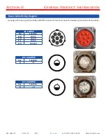
Page 23: ...uide www synqor com Power Cable Wiring Diagram Looking at the rear panel the MPS and MPPS connector terminals have the following functions and locations AC INPUT Pin Function A B Line 1 C D Line 2 E F Line 3 G H Ground A H F C B G D E DC OUTPUT Key Function A V A DC OUTPUT Key Function B V B ...

Page 24: ...NPUT cables first to the MPS or MPPS and then to the AC source Turn on the source if they have an up stream breaker Move the AC BREAKER on the rear panel of the MPS or MPPS to the ON position Start Up VERIFY that all connections to the MPS or MPPS are correct If the AC source is present and within specifications the three POWER IN LEDs on the front panel will be green Momentarily push the ON OFF s...

Page 25: ...or MPPS is turned on see Section I Warnings and the SET UP section above Similarly one should first turn off the MPS or MPPS and the source of input power before any power cables are disconnected from the MPS or MPPS ALSO NOTE that when the MPS or MPPS is turned on and delivering power to a load and then another piece of equipment is connected to the same output it is possible that this connection...

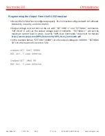
Page 26: ...mming the Output From the Web Interface Ensure the web interface is configured properly See the Ethernet SNMP user guide for details http www synqor com mps documents MPS_Ethernet_SNMP_UG pdf Navigate to the control tab The default address is http 169 254 1 1 control htm In the Configuration section enter the desired output voltage in mV click UPDATE For example 30000 corresponds to 30 000V output...

Page 27: ...and current can be set with SET VOUT x and SET IMAX commands SET VOUT x will set the output voltage level in millivolts SET IMAX x will set the maximum current level in amps See the MPS User Commands document for details http www synqor com MPS documents MPS_User_Commands pdf In the example below SET VOUT 30000 sets the output voltage to 30 000V SET IMAX 50 sets the maximum current to 50A SynQor S...

Page 28: ...and output power are such that the MPS or MPPS cannot otherwise maintain its specified maximum temperature for its internal circuitry the fans will momentarily be driven at a speed that exceeds their rated long term running speed If the ambient temperature is low enough for the level of power being delivered to the load the fans may not be on This is not a malfunction It is done to preserve the li...

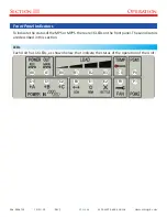
Page 29: ...nqor com Front Panel Indicators ToindicatethestatusoftheMPSorMPPS thereare16LEDsonthefrontpanel Theseindicators are described in this section LEDs Each Unit has 16 LEDs as shown below that indicate the status of the operation of the Unit A0 A1 B0 B1 B2 B3 C0 P0 D0 D1 D2 E0 E1 E2 F0 P1 ...

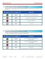
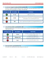
Page 30: ...is Not within Range Red Input is Not Present Off Unit is Off Power Out Indicators LEDs in positions A0 and A1 The LED in position A0 indicates the status of the Auxiliary DC OUTPUT and the LED in position A1 indicates the status of the Main DC OUTPUT according to the table below LED Appearance Description Indication Green Unit is On and the Output Voltage is Within Range Amber Unit is On but the O...

Page 31: ...Power 50 B0 B1 Green B2 Dimmed Green B3 Off Total Load Power 75 B0 B1 B2 Green B3 Dimmed Green Total Load Power 100 B0 B1 B2 Green B3 Blinking Red Total Load Power 100 MPS or MPPS Cooling System Indicator LED in position C0 The LED in position C0 indicates the temperature and status of the cooling system for the Unit according to the table below LED Appearance Description Indication Green Moderate...

Page 32: ...Recently Had Degraded Performance and Diagnostic Tests are Being Performed Red One or Both Fans Presently Have Degraded Performance Control Status LED in position E0 E1 E2 The LED in position E0 E1 or E2 indicates whether RS232 or Ethernet Port Remote Enable Shutdown or Battle Short are active LED Appearance Description Indication Green E0 RS232 active or Ethernet Port Active E1 Remote Enable Acti...

Page 33: ...ails 500 5 Low Pressure I II and III 15 000 ft operating 40 000 ft storage 501 5 High Temperature I and II 55o C operating 65o C storage 502 5 Low Temperature I and II 20o C operating 20o C storage 503 5 Temperature Shock I 10 cycles 10o C minute 506 5 Rain I 4 rain hour 40 mph wind velocity 507 5 Humidity NA 95 508 6 Fungus NA 28 day test 509 5 Salt Fog NA 5 salt solution 2 cycles 24 hr wet 24 hr...

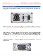
Page 34: ...mputer so that it can control the MPS or MPPS and receive information regarding the status of the MPS or MPPS The Configuration male DB15 connector on the right provides for synchronized startup and shutdown operation of Multiple Interconnected Units using the SYN 9322 or SYN 9323 cable ForMPPSUnits theConfigurationconnectoralsoprovidesactivecurrentsharing Seedescription Synchronized Operation of ...

Page 35: ...4 Input Pin 50k Ohms 50k Ohms 100 Ohms 5V 500 Ohms PS2581L 1N4148 6 Input Pin TTL 5V I O Circuits OUTPUT ON OUTPUT OFF 5V Pin SHUTDOWN Input Pin Remote On Off Switch SPDT Momentary ON OFF ON 100 Ohms 5V 8 500 Ohms 13 PS2581L 1N4148 REMOTE_START Input Pin 500 Ohms 12 PS2581L 1N4148 Internal User I O Circuits Remote On Off Switch Connections Note A 2PDT or 3PDT switch may be substituted for single c...

Page 36: ... is within range OVER_TEMP 15 Open collector output where low indicates that the MPS MPPS is at or above its maximum temperature With an internal 50 k Pull up Resistor to 5 V and ESD Protection Diodes Battle Mode disables internal over temperature shutdown limits in the MPS or MPPS hardware Battle Mode is indicated with a flashing red light in panel position E2 This mode can be commanded by pullin...

Page 37: ...interface provides a web page based user interface for monitoring and control of the MPS For MPPS Units the user can set the output voltage and output current with the Ethernet interface The interface also exposes an SNMP interface compliant to RFC 1628 The Ethernet interface supports 10BASE T and 100BASE T standards It utilizes a standard RJ 45 connector alsoallowingametallicsealablecircularmilit...

Page 38: ...at are also operating will disable their outputs at the same time Finally when an MPS restarts after a fault event it will coordinate its restart to be simultaneous with other MPS devices restarting during the same interval These features are enabled by default when the SYN 9322 orSYN 9323cable is utilized to interconnect multiple MPS devices The features can be disabled via the serial interface u...

Page 39: ...utilized to interconnect multiple MPPS devices The features can be disabled via the serial interface using the SYNCCON OFF command and this setting is stored in non volatile memory These features can also be disabled via the web interface Parallel Operation Current sharing When Parallel operation has the following requirements and characteristics Configuration cable SYN 9322 or SYN 9323 must be us...

Page 40: ...ear panel are exposed to the environment and these fans are also weather proof The Unit can therefore be cleaned without concern of getting liquids inside the chamber NOTE however that if the cables have been removed from the connectors the connectors should have their covers installed If they are not then care should be taken to not get excess liquid on the connector terminals ALSO NOTE that care...

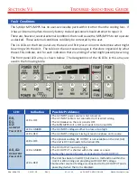
Page 41: ...array are used in the following table A0 A1 B0 B1 B2 B3 C0 P0 D0 D1 D2 E0 E1 E2 F0 P1 LED Indication Possible Problem s D0 D1 D2 AC INPUT Power LED LED is OFF The AC INPUT power source is not turned on The AC INPUT cable is not connected or it is wired wrong The AC Breaker on the rear panel is OFF The MPS MPPS Unit is OFF and needs to be turned ON LED is AMBER The AC INPUT voltage is either too lo...

Page 42: ...is no problem LED is AMBER Indicates that the fans are running at 100 of their rated speed There is no problem but the Unit is operating at a high ambient temperature and a high load combination LED is RED Fans are running at 110 of rated speed to keep the Unit cool The maximum recommended temperature may be exceeded but the fans are keeping things cool enough to avoid triggering the over temperat...

Page 43: ...ctive current sharing algorithm will not attempt to share with Units that have a different programmed output voltage Consider two Units in parallel If one is set to 28000 mV and the other is set to 28001 mV the active current sharing algorithm will not run Other possible situations that are the result of external issues that a user could likely correct are related to Loads that draw a large surge ...

Page 44: ...6 USA only SynQor Headquarters 155 Swanson Road Boxborough MA 01719 1316 USA www synqor com Made in USA Military Field Grade Power Supply Operator s Guide MPS 4000 Series MPPS 4000 Series 006 0006715 10 31 18 Rev J ...

Reviews: