getting started
1
9
Synrad
Firestar i401
operator’s manual
Mounting
3
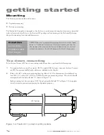
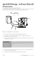
Carefully place the i401 laser on the mounting surface so the holes in the mounting feet line up over
the threaded holes in the mounting surface.
4
Place a split washer and flat washer on each capscrew and insert the fasteners through the feet into
the mounting surface. Turn the screws by hand until the threads fully engage.
5
Evenly tighten all four fasteners to a torque of 40 N m (29 ft lb
f
).
Note:
After the laser is fastened into position, you may remove the lifting handles if necessary.
Bottom up mounting
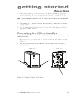
To fasten your Firestar i401 laser to a mounting surface from below, perform the following steps:
1
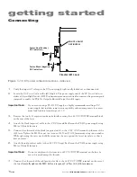
Unscrew the four M10 capscrews fastening the feet to the bottom of the i401 laser and remove the
factory-installed mounting feet.
2
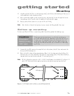
Refer to the i401 outline and mounting drawing (Sheet 2 of 2) for dimensions, then drill four 10.6
mm (close fit) or 11.2 mm (normal fit) thru holes in your mounting surface. These holes should cor-
respond with the fastener locations labeled “C” shown in Figure 1-5.
Note:
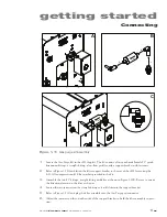
The i401 baseplate contains two 0.252" × 0.500" beam alignment slots (labeled “D” in Figure 1-5)
and a 0.252" dowel pin hole for applications that require precision positioning of the laser.
D
C
D
C
C
C
i401 Bottom View
Caution
possible
equipment
damage
When removing the mounting feet, raise the laser by placing sup-
port blocks under the baseplate.
Do not lay or place the i401 laser on
its side or top, even temporarily, because the sheetmetal covers are
not designed to support the weight of the laser. Always support and
mount the laser using the mounting feet or baseplate to avoid damag-
ing the laser.
Figure 1-5
Firestar i401 bottom up mounting locations

