getting started
1
18
Synrad
Firestar i401
operator’s manual
Connecting
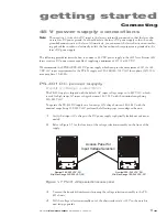
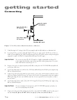
Figure 1-10
DC power connection locations – side view
1
Verify that input AC voltage to the DC power supply is physically locked out or disconnected.
2
Locate the
DC Power Cables
in the i401 ship kit. The power supply end of the
DC Power Cables
in-
cludes a 26-pin High Density (HD) D-subminiature connector wired for remote voltage sensing and
jumpered to enable the PS-401’s
Output Inhibit
and
Output Interlock
inputs.
Important Note:
If you are not using a PS-401 DC supply, we highly recommend installing a DC
power supply that includes remote sense capability and can compensate for a maxi-
mum load lead loss (round trip) of 1.0 V.
3
Remove the two 6–32 capscrews and acrylic shield covering the
+48 VDC POWER
terminal block
on the rear of the laser.
4
Attach the black (negative) cable to the
–
VDC Ground Bus Bar on the PS-401 power supply using
M6 (or 1/4 inch) fasteners.
5
Connect the other end of the black (negative) cable to the
–VDC GND
terminal on the rear of the
i401 laser. Tighten the M10 hex nut to a torque of 34 N m (25 ft lb
f
) maximum using two wrenches.
While tightening the outer nut, hold the inner nut, the one against the laser’s rear plate, so that it
does not move.
6
Attach the red (positive) cable to the
+
48 VDC Output Bus Bar on the PS-401 power supply using
M6 (or 1/4 inch) fasteners.
Important Note:
Do not overtighten the fastener into
+48 VDC POWER
terminal on the laser be-
cause this may damage the threads.
7
Connect the other end of the red (positive) cable to the
+48 VDC POWER
terminal on the rear of
the laser.
Carefully tighten the M10 bolt to a torque of 7.4 N m (5.5 ft lb
f
) maximum.
Fasten Black (Negative)
DC Cable Here …
Fasten Red (Positive)
DC Cable Here …
DO NOT ADJUST
OR TIGHTEN!
Firestar i401 Laser


