operation
2
2
Synrad
Firestar i401
operator’s manual
Controls and indicators
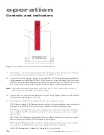
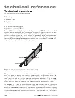
Figure 2-1
Firestar i401 front panel controls and indicators
1
Laser Aperture – provides an opening in Firestar’s front panel from which the beam exits. The open-
ing is threaded to accept beam delivery components with M29× 1.0 threads.
2
Optical Accessories Mounting – provides six threaded holes (8–32) for mounting optional beam de-
livery components available from SYNRAD. Because excessive weight may damage the laser, consult
SYNRAD before mounting components not specifically designed as Firestar options. Refer to
Firestar
i401 package outline drawings
in the Technical Reference chapter for mounting dimensions.
Note:
When mounting optical components to i401 lasers, the 8–32 UNC fasteners must extend no
further than 0.25" (6.35 mm) into the laser’s faceplate.
3
Aperture Seal – prevents dust from damaging laser optics during shipping. Remove the red self-adhe-
sive label before applying power to the laser.
4
Status
Indicators – LED indicators display i401 laser status. From left to right:
INT
(Remote Interlock) LED illuminates green to indicate the remote interlock circuit is closed and
lasing may be enabled; the LED is red and lasing is disabled if the interlock input is open.
TMP
(Temperature) LED illuminates green to indicate laser temperature is within limits and lasing
may be enabled; the LED is red and lasing is disabled if coolant temperature or flow rate is outside
operating limits.
RDY
(Ready) LED illuminates yellow when the laser is enabled, indicating that, after a five-second
delay, lasing will begin when a PWM Command signal is applied.
SHT
(Shutter) LED illuminates blue to indicate that the electromechanical shutter is Open and las-
ing is enabled. The
SHT
LED is off and lasing is disabled if the shutter is Closed.
LASE
LED illuminates red to indicate the Firestar i401 is actively lasing.
2
1
3

