operation
2
6
Synrad
Firestar i401
operator’s manual
Initial start-up
4
Start purge gas flow at a rate of 30–60 Standard Cubic Feet per Hour (SCFH) at a pressure not
to exceed 5 PSI (0.34 Bars) If a flowmeter is not available, set a purge pressure between 2–5 PSI
(0.14–0.34 Bars).
Note:
If you have not yet operated your UC-2000 Universal Laser Controller, refer to the
UC-2000
Laser Controller Operator’s Manual
for setup and operation instructions before continuing.
5
Set the UC-2000 to
MANUAL
mode, and then set the
PWM Adj Knob
to provide zero percent
output (0.0%). The UC-2000’s
Lase
indicator should be Off.
6
Turn on the +48 VDC power supply.
If the factory-wired
Quick Start Plug
is installed, the
INT
indicator will illuminate green, the
SHT
indicator will illuminate blue, and the
RDY
LED will illuminate yellow. The
TMP
indicator will il-
luminate green if laser temperature is within safe operating limits.
Starting your Firestar i401 laser
Important Note:
Unlike other Firestar lasers, the
SHT
LED on i401 lasers is dependent on the state
of the
RDY
indicator. Although a
Shutter Open Request
signal is applied, the
SHT
LED will not light while the
RDY
LED is Off. Therefore, no power is applied to the
RF boards until the
RDY
indicator is illuminated.
Important Note:
Each time an i401 OEM laser is powered up, a five-second delay occurs between the
time the
RDY
indicator illuminates and the i401 is permitted to lase. After the five-
second delay (and while the
SHT
LED is off), tickle is applied to maintain the laser
in a ready state. Once a
Shutter Open Request
signal is applied, and the
SHT
LED
illuminates, apply PWM Command signals to begin lasing.
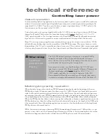
Warning
serious
personal
injury
Because of phase differences, external tickle pulses may combine
with the internally-generated tickle signal causing the
LASE
LED to
flicker during the transition from tickle to lasing. Laser output may
occur if the
LASE
LED flickers.
1
Press the UC-2000’s
Lase On/Off
button. The
Lase
indicator on the UC-2000 should illuminate.
2
Use the
PWM Adj Knob
on the UC-2000 Controller to slowly increase power. The
LASE
LED turns
red when PWM Command signal pulses are long enough to produce laser output (typically 7–10 µs
at 5 kHz). The spot where the beam hits the beam block increases in brightness to indicate increased
power output.
3
Press the UC-2000’s
Lase On/Off
button to stop lasing.
Lase
indicators on the UC-2000 and the laser
should both turn off.
4
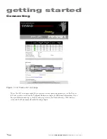
If you are connected to the i401’s
Ethernet
port, access the i401 web page to verify operating condi-
tions and functionality (refer back to Figure 1-12). See the Getting Started or Technical Reference
chapters for details on accessing the Firestar i401 web page.

