operation
2
8
Synrad
Firestar i401
operator’s manual
Initial start-up
3
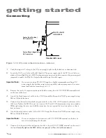
Turn on the chiller and set the temperature setpoint between 18 °C–22 °C. Verify that the chiller
is delivering a flow rate of 4 GPM at less than 60 PSI of pressure. Examine all cooling connections
carefully and ensure that they do not leak.
Warning
serious
personal
injury
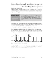
Because of phase differences, external tickle pulses may combine
with the internally-generated tickle signal causing the
LASE
LED to
flicker during the transition from tickle to lasing. Laser output may
occur if the
LASE
LED flickers.
Caution
possible
equipment
damage
Do not exceed a gas purge pressure of 5 PSI (0.34 Bars). Excessive
pressure may damage the purge assembly or other internal laser com-
ponents.
Do not use argon as a purge gas. Use only nitrogen or clean, dry air as
described in Table 1-3,
Purge gas specifications
.
4
Start purge gas flow at a rate of 30–60 Standard Cubic Feet per Hour (SCFH) at a pressure not
to exceed 5 PSI (0.34 Bars) If a flowmeter is not available, set a purge pressure between 2–5 PSI
(0.14–0.34 Bars).
5
Ensure that your PWM controller is set to zero percent output (0.0%).
6
Turn on the +48 VDC power supply.
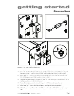
If the factory-wired
Quick Start Plug
is installed, the
INT
indicator will illuminate green, the
SHT
indicator will illuminate blue, and the
RDY
LED will illuminate yellow. The
TMP
indicator will il-
luminate green if laser temperature is within safe operating limits.
Starting your Firestar i401 laser
Important Note:
Unlike other Firestar lasers, the
SHT
LED on i401 lasers is dependent on the state
of the
RDY
indicator. Although a
Shutter Open Request
signal is applied, the
SHT
LED will not light while the
RDY
LED is Off. Therefore, no power is applied to the
RF boards until the
RDY
indicator is illuminated.
Important Note:
Each time an i401 OEM laser is powered up, a five-second delay occurs between the
time the
RDY
indicator illuminates and the i401 is permitted to lase. After the five-
second delay (and while the
SHT
LED is off), tickle is applied to maintain the laser
in a ready state. Once a
Shutter Open Request
signal is applied, and the
SHT
LED
illuminates, apply PWM Command signals to begin lasing.
1
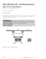
Apply a PWM Command signal (+5 VDC, 5 kHz square wave of 4 µs duration) between
PWM Input
(Pin 9) and
PWM Return
(Pin 1) on Firestar’s
User I/O
connector.

