technical reference
3
2
Synrad
Firestar i401
operator’s manual
Technical overview
The
Technical overview
section includes subsections:
■
Laser design
■
RF power supply
■
Optical setup
Laser design
Optical resonator
Firestar
®
i401 lasers were developed using new technology developed by SYNRAD, Inc. This new technol-
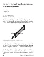
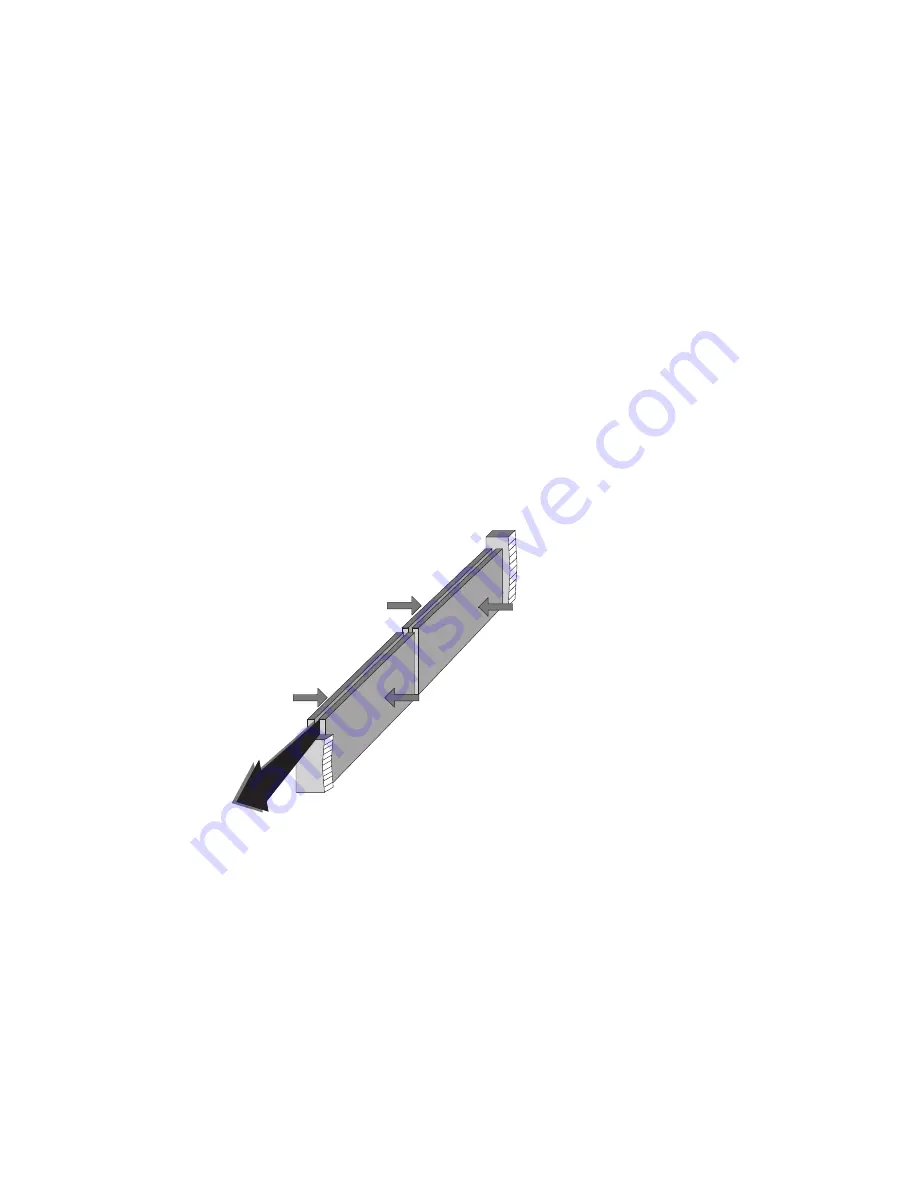
ogy, based on an hybrid waveguide/unstable resonator design (Figure 3-1), enables SYNRAD to economi-
cally produce a symmetrical laser beam from a small but powerful laser capable of operating for many
years with virtually no maintenance. Firestar’s unique extruded aluminum envelope offers excellent heat
transfer, long gas life, and low operating costs in contrast to other laser tube technologies. Besides being
the vessel that maintains the lasing environment, the aluminum tube is also the structural platform that
integrates the laser’s optical, electrical, and cooling components.
Figure 3-1
Hybrid waveguide/unstable resonator design
The optical resonator, in conjunction with the electrodes and the gas mixture, generates the laser beam.
Firestar i401 optical resonators are comprised of three optical elements: a front mirror, a rear mirror, and
an output window. These optical elements are fastened to the tube’s exterior and are exposed to its interior
through holes in the end caps. O-rings are sandwiched between optical elements and the end cap to form
a gas seal and to provide a flexible cushion that allows the slight movement necessary for alignment. All
optical elements are aligned and locked into place by factory technicians before the laser is shipped.
The structure of the resonator and internal beam conditioning optics combine to produce a near Gaussian
mode quality (M
2
factor) of < 1.2. Beam waist diameter is 6.0 mm at the output aperture and full-angle
divergence due to diffraction is approximately 2.3 milliradians (a 2.3 mrad divergence means that beam di-
ameter increases 2.3 mm over every one meter distance traveled). Beam ellipticity measures approximately
< 1.2 as it exits the resonator, but becomes closer to 1.0 in the far field (or at the point of focus) as shown
in Figure 3.2.
RF Generator
RF Generator
RF Generator
RF Generator
Laser Output


