technical reference
3
6
Synrad
Firestar i401
operator’s manual
Warning
serious
personal
injury
Because of phase differences, external tickle pulses may combine
with the internally-generated tickle signal causing the
LASE
LED to
flicker during the transition from tickle to lasing. Laser output may
occur if the
LASE
LED flickers.
Controlling laser power
The
Controlling laser power
section includes subsections:
■
Control signals
■
Operating modes
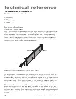
Control signals
Much of the information provided in this section describes the use of a SYNRAD UC-2000 Universal
Laser Controller to provide PWM Command signals to the i401 laser. If using an alternate method of laser
control, thoroughly review this section,
Controlling laser power
, as well as the following section,
User I/O
connections
, for an understanding of the signal requirements necessary to control Firestar lasers. For more
information about the UC-2000, please consult the
UC-2000 Laser Controller Operator’s Manual
.
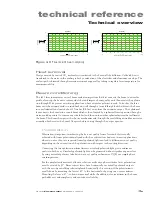
Tickle pulse
Tickle pulses pre-ionize the laser gas to just below the lasing threshold so that a further increase in pulse
width adds enough energy to the plasma to cause laser emission. Tickle pulses cause the laser to respond
predictably and almost instantaneously to PWM Command signals, even when there is considerable delay
(laser off time) between applied Command signals. All Firestar i401 lasers incorporate a built-in tickle
generator, freeing customers from the need to supply external tickle pulses between lasing commands.
Internal circuitry monitors the incoming PWM signal and determines the amount of time the laser was
on (lasing) during the last 200 microsecond (µs) interval. If the laser’s on time was greater than the preset
tickle value, then no tickle pulse is generated because the PWM signal was sufficient to maintain a plasma
state. If no PWM signal was applied during the 200-µs measurement period (or was
shorter
than the preset
tickle value), internal circuitry generates a tickle pulse such that the laser always receives a pre-set amount
of RF drive averaged over any 200-µs interval.
Pulse Width Modulation (PWM)
Pulse Width Modulation, or PWM, controls laser power by varying the duty cycle of Firestar’s RF ampli-
fiers, which in turn control the time-averaged RF power applied to the laser. The percentage of optical
output increases as duty cycle increases (at a constant PWM frequency) or as PWM frequency decreases
(at a constant duty cycle).
Firestar i401 lasers are designed to operate at Command signal base frequencies up to 100 kHz; however,
the choice of PWM frequency depends on the user’s specific application. In the majority of laser applica-
tions, the UC-2000’s default Command signal frequency of 5 kHz has proven to work well. When con-
sidering Command frequencies at 5 kHz or below, please review
Marking/engraving operation
later in this
section. For high-speed motion applications that cannot tolerate any ripple in the optical beam response
but still need adjustable power levels, we recommend the use of higher PWM frequencies, up to 100 kHz
maximum.

