technical reference
3
9
Synrad
Firestar i401
operator’s manual
Controlling laser power
Gated operation
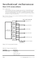
In many marking and cutting applications, the laser is required to pulse, or gate, on and off in synchroni-
zation with an external control signal (typically from a computer or function generator operating in the
range from DC to 1 kHz). To pulse or gate the laser, connect a signal pro5.0 VDC pulses to the
Gate
connector on the rear panel of the UC-2000.
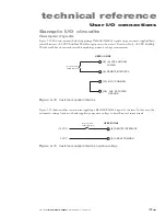
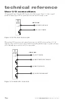
Users who intend to use a gating signal should set the UC-2000’s gate input logic to internal Pull-Down
(normally off) mode. This prevents the beam from being enabled unless a high level (+3.5 V to +5.0
VDC) signal is applied to the
Gate
input connector. In the pull-down (normally off) mode an asserted
logic low state, short circuit to ground, or an open or disconnected
Gate
input locks the beam off.
Many CO
2
lasers operating in applications requiring short gating pulses at repetition rates below 500 Hz
will exhibit some leading edge overshoot regardless of the PWM frequency. This occurs because a cooler
lasing medium (the CO
2
gas) is more efficient than a hotter one. This overshoot effect is more pronounced
at lower gating frequencies since the gas has a longer time to cool down between Command signal pulses.
Warning
serious
personal
injury
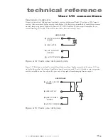
The UC-2000’s default gate logic is factory set to internal Pull-Up
(normally on) mode so that an open (disconnected)
Gate
input
causes the laser to turn on. This functionality allows the user to easily
test and verify laser operation prior to integration.
In an integrated system, you should configure the UC-2000’s gate
input logic to internal Pull-Down (normally off) mode. This prevents
the beam from being enabled unless a high level (+3.5 V to +5.0
VDC) signal is applied to the
Gate
input connector. In the Pull-
Down (normally off) mode an asserted logic low signal, short circuit
to ground, or an open or disconnected
Gate
input locks the beam off.
Marking/engraving operation
When the delay between the end of one PWM Command signal pulse and the beginning of the next
PWM pulse exceeds 200 microseconds (less than or equal to 5 kHz), Firestar’s on-board tickle generator
sends a tickle pulse to maintain plasma ionization in the tube. Because the on-board tickle generator can
not anticipate when the next PWM Command pulse will arrive; the tickle pulse (which typically lasts for
2–6 µs depending on the laser) can effectively merge with a PWM signal that follows closely afterwards.
When the PWM pulse that follows is short, causing the tickle pulse to become a significant fraction of the
PWM pulse duration, then the tickle pulse effectively substantially increases the length of the PWM pulse
it has merged with. For subtle marking applications on sensitive, low threshold materials this lengthened
PWM pulse may affect mark quality.
While this situation can occur when using PWM Command signal frequencies of 5 kHz and less, it is im-
portant to note that it isn’t the Command signal frequency itself that is the determining factor but rather
this behavior happens only when the off time between PWM pulses exceeds 200 microseconds.

