technical reference
3
15
Synrad
Firestar i401
operator’s manual
User I/O connections
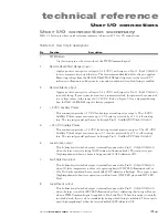
Pin 10 Shutter Open Request
Apply a positive or negative voltage (±5–24 VDC) with respect to Pin 11,
Input Common
, to
open the internal electromechanical shutter assembly (when the
Remote Interlock
input is ac-
tive). If your system does not supply a
Shutter Open Request
signal, then this pin must be con-
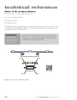
nected to a voltage source in the range of ±5–24 VDC. Refer to Figure 3-7 for a diagram show-
ing how the
Shutter Open Request
input is factory-jumpered. See Table 3-4 for input circuit
specifications.
Note:
Shutter Open Request
and
Remote Interlock
inputs are dependent control functions.
The internal shutter mechanism will
not activate (open) until a voltage is also applied
to the
Remote Interlock
input (causing
INT
LED to illuminate green and
RDY
LED to
turn On).
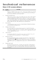
Pin 11 Input Common
Use this pin to connect return lines for
Remote Interlock
,
Shutter Open Request
, and
Remote
Reset/Start Request
lines. Refer to Table 3-4 for input circuit specifications.
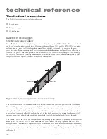
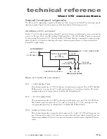
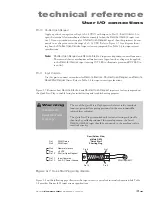
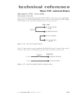
Figure 3-7 illustrates how
Remote Interlock
and
Shutter Open Request
inputs are factory-jumpered on
the
Quick Start Plug
to enable lasing for initial testing and troubleshooting purposes.
Pin 1
PWM Return
Pin 9
PWM Input
Pin 3
Remote Interlock
Pin 4
+5 VDC
Pin 10
Shutter Open Request
Pin 11
Input Common
Pin 12
Aux. DC Power Ground
Pin 15
Pin 9
Pin 8
Pin 1
PWM Input BNC
Rear (Solder Side)
of Male DB15
"Quick Start"
Shorting Plug
Warning
serious
personal
injury
The use of the
Quick Start Plug
bypasses the laser’s safety interlock
function, potentially exposing personnel in the area to
invisible
infrared laser radiation.
The
Quick Start Plug
is intended only for initial testing and trouble-
shooting by qualified personnel. In normal operation, the laser’s
Remote Interlock
input should be connected to the machine’s safety
interlock circuitry.
Figure 3-7
Quick Start Plug wiring diagram
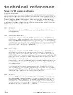
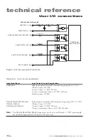
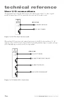
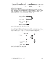
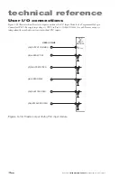
Figure 3-8 on the following page illustrates the input circuit’s equivalent internal schematic while Table
3-4 provides Firestar i401 input circuit specifications.

