technical reference
3
18
Synrad
Firestar i401
operator’s manual
User I/O connections
Pin 15 Interlock Open
This bi-directional switched output is internally connected to Pin 13,
Output Common
, when
remote interlock input circuitry is open (
INT
indicator red), indicating that lasing is disabled.
This output is open (high impedance) when the laser is enabled (
INT
indicator green). When
this output is initially switched open, there is a five-second delay during which lasing is inhibited.
See Table 3-5 for output circuit specifications.
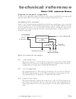
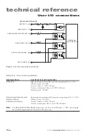
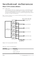
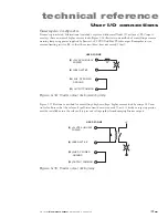
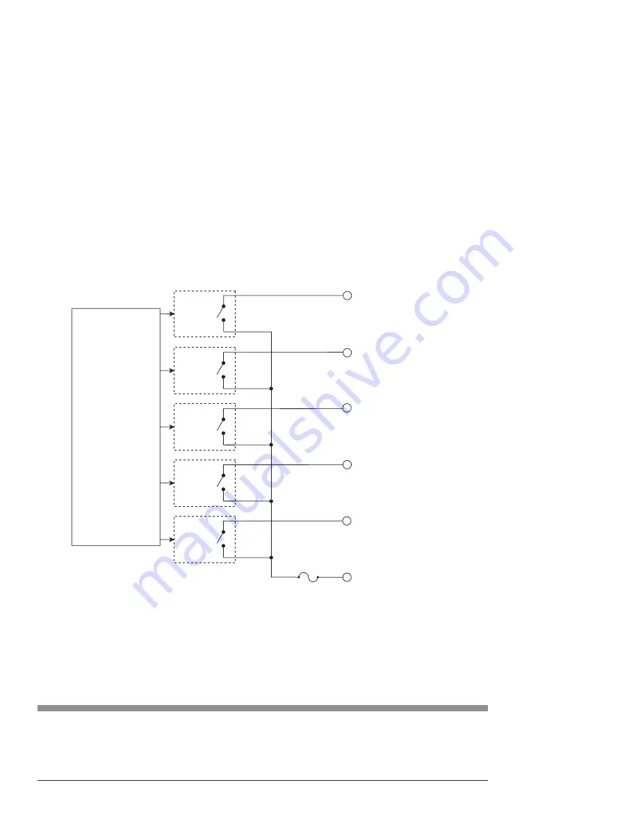
Figure 3-9 illustrates the output circuit’s equivalent internal schematic and Table 3-5 provides Firestar
i401 output circuit specifications.
FIRESTAR i401
OUTPUT CIRCUITRY
USER I/O OUTPUT SIGNAL PINS
SOLID
STATE
RELAY
SOLID
STATE
RELAY
SOLID
STATE
RELAY
SOLID
STATE
RELAY
SOLID
STATE
RELAY
0.3 A FUSE,
SELF-RESETTING
(6) LASER ACTIVE
(7) FAULT DETECTED
(8) LASER READY
(14) SHUTTER OPEN
(15) INTERLOCK OPEN
(13) OUTPUT COMMON
Figure 3-9
Output equivalent schematic
Table 3-5
Output circuit specifications
Output Device
Specifications
Bi-directional MOSFET
2.5 Ohms Rdson
10 MOhms Off
Voltage ±24 VDC, max.
Current 50 mA, max.


