technical reference
3
30
Synrad
Firestar i401
operator’s manual
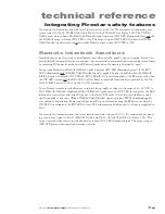
Firestar i401 general specifications
Table 3-6
Firestar i401 general specifications
Parameter
Firestar
i401
Output Specifications
Wavelength ...................................................10.2–10.7 microns
Power Output
1, 2
Continuous
............................................400 Watts
Pulsed
3
....................................................440 Watts
Power Stability
4
.............................................± 7%
Power Stability
5
.............................................± 5%
Mode Quality
6
...............................................M
2
< 1.2
Beam Waist Diameter (at 1/e
2
)
7
....................6.0 ± 0.6 mm
Diameter at faceplate, (1/e
2
) ..................8.0 ± 1.0 mm
Beam Divergence, full angle, (at 1/e
2
) .........2.5 ± 0.3 mrad
Ellipticity .......................................................< 1.2
Polarization ...................................................linear, rotated 45°
Extinction Ratio ............................................> 100:1
Rise Time
8
.....................................................< 100 µs
Modulation (Optical response) ....................up to 100 kHz
Input Specifications
Power Supply
Voltage
...................................................48 V ±0.5 VDC
Maximum Current
9
................................125 A
Inrush Current (max.) ...........................170 A for < 10 ms
Command Input Signal
Voltage ..........................................................+3.5 to +6.7 VDC
Current (max., continuous) ..........................10 mA @ +6.7 VDC
Frequency ......................................................DC–100 kHz
Duty Cycle ....................................................0–100%
Logic Low State (Vmin–Vmax.) ..................0.0 to +0.8 VDC
Logic High State (Vmin–Vmax.) .................+3.5 to +6.7 VDC
* Specifications subject to change without notice.
1 This power level is guaranteed for 12 months regardless of operating hours.
2 48 VDC input voltage to obtain guaranteed output power.
3 100 Hz, 10% duty cycle, average power as read by laser power meter, then multiplied by 10.
4 From cold start (tube at 20 °C for 30 minutes before start) at 99% duty cycle with 4 GPM flow and 20 °C coolant temperature.
5 After two minutes (typical) at 99% duty cycle, 4 GPM flow, and 20 °C coolant temperature.
6 Measured at 99% duty cycle, 5 kHz, and 20 °C coolant temperature after 30 minute warm-up.
7 Measured at beam waist. See the laser’s
Final Test Report
for beam waist location.
8 Measured at 100 Hz, 10% duty cycle.
9 Measured at 48 VDC input, 100% duty cycle.

