maintenance/
troubleshooting
4
7
Synrad
Firestar i401
operator’s manual
Troubleshooting
Operational flowchart
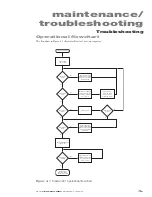
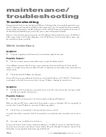
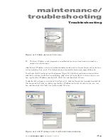
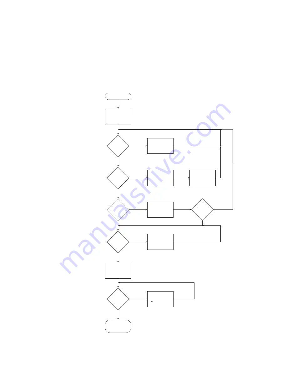
The flowchart in Figure 4-1 illustrates Firestar’s start-up sequence.
Figure 4-1
Firestar i401 operational flowchart
Yes
No
INT
indicator
Green?
TMP
indicator
Green?
SHT
indicator
Blue?
RDY
indicator
Yellow?
RDY
indicator
Yellow?
Apply interlock signal
to
Remote Interlock
input
or install factory-supplied
Quick Start Plug
Check that cooling water
is flowing through laser
and that coolant temp
is below 22° C
Apply shutter open
signal to
Shutter Open
Request
input or install
factory-supplied
Quick
Start Plug
Cycle DC power
Apply PWM Command
signal to laser
Apply 48 VDC
power to laser
LASE
indicator
illuminates Red to
indicate laser output
Laser Start Sequence
Yes
Yes
Yes
No
No
No
Yes
No
Cycle DC power
(remove DC power,
wait 15 seconds,
reapply DC power)
SHT
indicator
Flashing?
Apply tickle pulses or a
PWM Command signal
(< 5% duty cycle) for
30 to 60 seconds
No
Yes

