background image


The magic of the Q169 module is the modulation possibilities and their easy access.  Modulation is just a 

fancy word for having one signal change something about another signal.  For each oscillator, three 

things can be modulated 

-

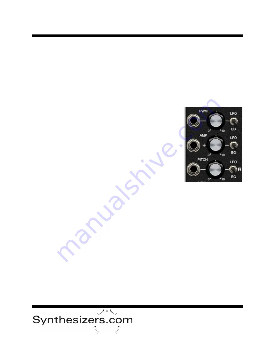
 Pulse width, waveform amplitude, and pitch.  These three things can be modu-

lated by the LFO, by the Envelope Generator, by the other oscillator, by an external signal into the jack, or 

manually controlled by the knob.  The possibilities are amazing, and most don't require patch cables.


Pulse Width (PWM)


The width of the pulse waveform is controllable and has a nice effect on the sound, like phase shifting.  

The oscillator's pitch stays the same but the waveform appears to our ears as moving.  PWM only applies 

to the pulse waveform.


The toggle switch determines the source of the modulation.  Options are 

LFO or EG (Envelope Generator).  When LFO or EG is selected, the knob 

provides control over the attenuation (strength of the effect). 


The center toggle switch position is off and then the knob gives you man-

ual control over the pulse width from 0 to 50%.  Since an inverted wave-

form sounds the same to our ears, 50% to 100% sounds the same.  If you 

need an inverted form of the pulse for modulation purposes, use the IN-

VERT switch.


A jack is provided for an external signal to control the pulse width.  When 

a plug is inserted, the toggle switch sources are bypassed and the knob 

provides attenuation. The external signal can come from another module 

or perhaps the S&H output on the Q168 Aid module, or possibly noise or 

another waveform from the other oscillator.


Amplitude


Each oscillator on the Q169 has a built

-

in VCA (amplifier) to provide con-

trol over the waveform amplitude. This provides many possibilities not found on other oscillators such as 

using the module as a stand

-

alone voice with the VCAs controlled by the internal EG, or by creating FM

-

style operator synthesis where pitch and amplitude modulation provides amazing new sounds.  All of this 

is easy with Osc+.


The toggle switch determines the source of modulation.  When LFO or EG is selected, the knob provides 

attenuation.  When the toggle switch is in the center, the knob provides manual control of the amplitude 

-


this is basically a volume control.  


A jack is provided for an external signal to control amplitude.  This signal is added to the other sources as 

indicated by the panel graphics. Use the jack to modulate from the other VCO.


Pitch


The toggle switch provides the source of pitch modulation 

-

 LFO, EG, or the other VCO.  The knob pro-

vides attenuation in each position.  When an external signal is plugged into the jack, the toggle switch 

source is bypassed and the knob becomes the attenuator for it.


The result of pitch modulation is dramatic, especially when having both oscillators modulate each other.  

Experimentation is the only way to fully appreciate this.  


When selecting position [2] on the toggle switch, make sure oscillator #2 has its AMP turned on.


Modulation Section


Q169 

 Osc+


Summary of Contents for Q169 Oscillator++

Page 1: ...and amplitude at the same time and in variable amounts A cross modulation extravaganza The Q169 is the equivalent of 10 modules and 20 patch cables arranged in a musically useful and understandable way Configura tions you probably wouldn t patch naturally are easily accessible Oscillator is com plexity dignified The optional Q168 Aid module provides patch points for LFO waveforms the enve lope noi...

Page 2: ...de with easy connection to the LFO EG and external signals Q169 Oscillator Individual outputs and mixed output LFO and Envelope Generator Gate for triggering envelopes and syncing LFO and oscillators Oscillator 1 modulation settings Oscillator 2 tuning and range waveform select sync select Sample Hold Oscillator 2 modulation settings Oscillator 1 with VCA Oscillator 2 with VCA 1V Octave pitch CV f...

Page 3: ...witch Jack LFO 5V EG AMP IN AMP Pot Switch Jack AMP IN Mix Out LED Triangle VCO 2 Wave Shapers VCA Out Freq Pot 1V Oct Range Sw Wave Selector LFO EG VCO1 Pitch modulation IN Pitch Pot LFO 5V EG PWM IN PWM Pot Switch Jack LFO 5V EG AMP IN AMP Pot Switch Jack AMP IN Mix Decay VCI LED LED S H AS ASR Speed EG Gate In Out Clk Sample Hold Gate VCO1 Gate VCO2 LFO Speed Range Sync Sync Normal from 1 Slew ...

Page 4: ...s by 2 octaves and access to oscillator 1 s linear pitch signal is provid ed Q169 Oscillator 2 volt source to provide 2 octave transposition of oscillators Independent signal at tenuator with inversion and offset Can be used as a voltage source Direct access to the sample hold output whose source is oscillator 1 and clocked by the LFO Access to the LFO sine and square waveforms Gate Sync switch co...

Page 5: ...ke subtracting a sine wave from a triangle wave and produces interesting harmonics The next section is the modulation matrix This arrangement gives you easy access to amazingly com plex cross modulation between the two oscillators pitch pulse width and amplitude The PITCH jacks at the bottom are 1V Octave scaling to track a standard keyboard VCO 1 s jack is automatically connected to VCO 2 s jack ...

Page 6: ...n when a plug is inserted into VCO 2 s jack A typical use for this jack is a pitch bend wheel Pitch with Glide Second from the bottom pitch jack is also 1V per octave scaling A knob controls glide time for the control voltage signal This feature can also be referred to as portamento or slew limiting VCO 1 s pitch input is normal ized to VCO 2 s pitch input and broken in the same way as the pitch j...

Page 7: ...r to the other oscillator Typically a slower oscillator will sync the faster oscillator for the best effects Oscillator 1 is typically used as the slower oscillator The bottom position causes the waveform to sync to the GATE IN jack This is useful when using an oscillator as a modulator where each press of a key produces the same waveform progression Sync Oscillator 2 can be controlled by the inte...

Page 8: ...nob provides attenuation The external signal can come from another module or perhaps the S H output on the Q168 Aid module or possibly noise or another waveform from the other oscillator Amplitude Each oscillator on the Q169 has a built in VCA amplifier to provide con trol over the waveform amplitude This provides many possibilities not found on other oscillators such as using the module as a stan...

Page 9: ...e jack will trigger the envelope but the LFO can also trigger the envelope by setting the first toggle switch to LFO The envelope can be either Attack Decay or Attack Sustain Release as set by the AD ASR switch In the AD position the envelope will trigger at the beginning of the gate then when the peak is reached begins decay regard less of the gate s status typically a keypress In the ASR positio...

Page 10: ... pitch normalization reduces the need for multiples and patch cables Set pitch range however you d like Notice the S H is turned OFF and the Pitch modulation knobs are 0 Adjust the EG controls to your taste This patch performs as a complete synth voice From this humble beginning you can experiment with PWM from the LFO pitch modulation from LFO EG or the other oscillator VC inverting sync ing and ...

Page 11: ...ws that the source is the other oscillator Then set the knob to the de sired amount Start with very small amounts Take audio out from the center output jack and turn the output mixer to hear one or both of the oscillators Tune to your liking experimenting is where the magic happens In this patch the amplifiers are turned fully on and you can use an external VCA EG to control that Dual Oscillator C...

Page 12: ...ut controls the polarity of the other oscillator s waveform In this particular patch the amplifiers are set to full for use with an ex ternal VCA EG but you can also use the internal EG to control them for stand alone operation VC Inversion Patch Audio Output Pitch voltage from keyboard OFF SLOW 1 2 3 ...

Page 13: ... H circuit takes its input from VCO 1 and is clocked by the internal LFO The output controls the pitch of VCO 2 Flip the S H toggle switch up to turn it on Set the AMP on VCO 1 to control the amount of the pitch control The LFO speed controls how often the S H is triggered Normally in this type of patch you want to only listen to VCO 2 Sample and Hold Patch Audio Output Pitch from keyboard OFF SLO...

Page 14: ......

Reviews: