background image


Synway Information Engineering Co., Ltd


independent jacks. If you want to construct lines by yourself, please follow Figure 2-1 to connect 
each channel with corresponding pins. 

¾

 FXM-16A/PCIe 

A single board has four RJ45 jacks, each of which can be converted via a special 4-way hub or 
constructed by yourself to connect with 4 analog channels. See Figure 2-13 below for the structure 
of the 4-way hub. 


Figure 2-13 4-way Hub


See Table 2-4 for the correspondence between the on-board channels, the 8 pins in an RJ45 jack 
and the 4 interfaces of a 4-way hub. 

Jack 

Channel No.

Pins in RJ45   

4-way Hub 

1 1

st

 and 2

nd

 pins 

1

st

 interface 

2 3

rd

 and 4

th

 pins 

2

nd

 interface 

3 5

th

 and 6

th

 pins 

3

rd

 interface 

RJ45 

4 7

th

 and 8

th

 pins 

4

th

 interface 

Table 2-4 Correspondence between Channels, Pins in RJ45 and Interfaces of 4-way Hub 

Step 3:  Connect to the ringing current & battery feed power supply 

Note: Skip this step if FXS (station module) is not used in the system. 

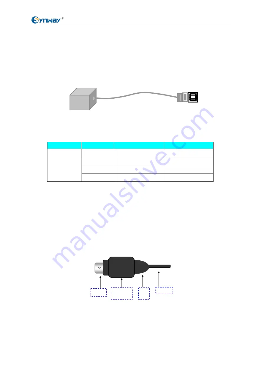
If you are using the external ringing current & battery feed power supply from Synway, note that 
the plug has a peculiar design for the prevention of improper insertion and extraction. The correct 
way is to hold the plug body (not the locking ring, or it cannot be fully inserted) when inserting the 
plug home into the socket, and to grasp the locking ring (not the plug body or the conductor) when 
pulling the plug out from the socket. See Figure 2-14 below. 


Figure 2-14 Plug Structure


Step 4:  Set up an application environment 

Connect phone lines with the port to an FXO module and the telephone with the port to an FXS 

Metal Ring 

Locking Ring

(movable)


Plug 

Body

3  

4  

2

Conductor

Synway FXM series Hardware Manual

Version 1.0


 Page 11 

Summary of Contents for FXM-16A/PCIe

Page 1: ...Synway AST Series FXM 8A PCI FXM 16A PCIe Version 1 0 Synway Information Engineering Co Ltd www sanhuid com...

Page 2: ...le 3 Chapter 2 Installation 5 2 1 Hardware Structure 5 2 2 Module Identification 6 2 3 Interface Identification 8 2 3 1 RJ11 8 2 3 2 RJ45 8 2 4 Slot Compatibility 9 2 5 System Requirements 10 2 6 Hard...

Page 3: ...is manual you agree to the following Software License Agreement Synway reserves the right to revise this manual without prior note Please contact Synway for the latest version of this manual before pl...

Page 4: ...n Engineering Co Ltd Revision History Version Date Comments Version 1 0 2009 02 Initial pubication Note Only major revisions to this manual itself recorded herein Synway FXM series Hardware Manual Ver...

Page 5: ...t applicable to secondary development Figure 1 1 is a typical application model with FXM xxx represents the existing and future board models in the FXM series Figure 1 1 Typical Application FXM 8A PCI...

Page 6: ...wling and minimizing the possibility of registering wrong DTMF and busy tones in a conference call designed especially for VoIP application environments z Voice CODEC Support Supports the hardware bas...

Page 7: ...zing the possibility of registering wrong DTMF and busy tones in a conference call designed especially for VoIP application environments z Voice CODEC Support Supports the hardware based A law law cod...

Page 8: ...r Analog Line Interface Circuit Subscriber Line Interface Circuit Voltage Detector Ring Detector Ring Control Hook Detector Echo Canceler Trunk Board Subscriber B d Outbound Voice Phone Interface CODE...

Page 9: ...odule Slot4 Ch7 Ch8 P R Ch1 Ch2 Ch3 Ch4 Ch5 Ch6 Ch7 Ch8 Led Jack 1 2 3 4 5 6 7 8 Figure 2 1 FXM 8A PCI Left and Front Views Note As shown in Figure 2 1 above the numbers for led jacks from left to rig...

Page 10: ...proof circuit that reaches the telecom standard and three of them at the same time z FXO Trunk Module Th module is equipped with connects its corresponding channel directly to local lines from Centra...

Page 11: ...up to 5 5km Refer to Figure 2 7 and Figure 2 8 for hardware structure Figure 2 7 Front View Figure 2 8 Rear View z Composite Module A composite module accommodates a trunk channel and a station chann...

Page 12: ...ent module interface may be FXO FXS or composite module Jacks 1 4 from top to bottom correspond to Modules 1 4 A single board of FXM 8A PCI can be equipped with up to 4 dual channel modules and suppor...

Page 13: ...PCI Slot Slot Number 0 AGP Pro Slot 1 64 bit 5 0V PCI Slot 2 64 bit 3 3V PCI Slot 3 32 bit 5 0V PCI Slot 4 PCI E Slot The FXM 8A PCI board includes PCI 2 2 bus with burst data transmission rate up to...

Page 14: ...to 2 channels The two leads in the middle constitute a port and the outer two leads set up another See Table 2 1 above for the pin layout and the corresponding channel number Each RJ11 jack can be co...

Page 15: ...4 Correspondence between Channels Pins in RJ45 and Interfaces of 4 way Hub Step 3 Connect to the ringing current battery feed power supply Note Skip this step if FXS station module is not used in the...

Page 16: ...td module to establish an application environment Step 5 Boot your computer and install the driver Regarding driver installation refer to the file SynAST UserManual doc for details Synway FXM series H...

Page 17: ...1M 500V DC 10k 1000Hz AC Storage humidity 8 90 non condensing Insulation resistance for PC isolation from telephone line 2M 500V DC Input output Interface Ringing current battery feed power supply jac...

Page 18: ...90 non condensing Storage humidity 8 90 non condensing Insulation resistance for PC isolation from telephone line 2M 500V DC Input output Interface Telephone line impedance Telephone line jack Four 8...

Page 19: ...about Asterisk please keep touch with Digium Inc for help Headquarters Synway Information Engineering Co Ltd http www synway net 9F Synway D R Center No 3756 Nanhuan Road Binjiang District Hangzhou P...

Reviews: