Device
Functions
©
SYS TEC electronic GmbH 2007 L-1032e_9
33
4.2.5
LED Interface Status Display
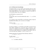
The LED interface is used to indicate the operational states for CAN
and Ethernet using the LEDs. The UDP or TCP interfaces displayed
on the status LEDs have to be selected. No selection is possible for
CAN, but the interface has to be configured.
An LED interface is generated with
mkif led
.
The directory name is selected automatically and is
/if/led0
for the
interface.
It is possible to select which LEDs go with which interface using the
adjustable filter defines (
refer to section 4.3
). Example:
With the setting
/if/led0/fin +hd1 +ld23
the states of interface 1 are assigned to the LEDs for CAN error and
CAN traffic (identified by
hd
) and the states of interface 2 and
interface 3 are displayed on the BTP error and BTP connection LEDs.
The states of other interfaces are not displayed. The interface IDs can
be accessed with the command
ls
(refer to section 4.5.2).
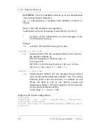
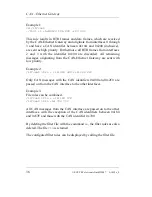
Default setting (the CAN interface has the interface number 1):
/if/led0/fin +hd1 +l
Possible options:
<option> ::={<reset>}
reset
re-initializes the LEDs
Summary of Contents for GW-003
Page 5: ...Contents SYS TEC electronic GmbH 2007 L 1032e_9 Index 97 ...
Page 8: ...CAN Ethernet Gateway SYS TEC electronic GmbH 2007 L 1032e_9 ...
Page 14: ...CAN Ethernet Gateway 6 SYS TEC electronic GmbH 2007 L 1032e_9 ...
Page 56: ...CAN Ethernet Gateway 48 SYS TEC electronic GmbH 2007 L 1032e_9 ...
Page 66: ...CAN Ethernet Gateway 58 SYS TEC electronic GmbH 2007 L 1032e_9 ...
Page 100: ...CAN Ethernet Gateway 92 SYS TEC electronic GmbH 2007 L 1032e_9 ...
Page 108: ...Published by SYS TEC electronic GmbH 2007 Ordering No L 1032e_9 Printed in Germany ...

