background image

CAN – Ethernet Gateway 


34


©

 SYS TEC electronic GmbH 2007     L-1032e_9 


4.3


Filtering 

4.3.1


Concept of Message Filtering 

The filtering is based on the screening of CAN identifiers. The CAN-
Ethernet Gateway processes the data from the Ethernet or CAN in a 
data pool. The filter rules determine which messages will be passed on 
from this data pool. Thus data traffic can be reduced if, for example, 
only messages from a certain group of CAN identifiers (CAN IDs) are 
passed on. Furthermore, individual CAN identifiers can be selected for 
highly specific filtering schemes. 
 
The filter rules can be determined by calling an interface's filter files. 
If no filter rules are present then all messages are passed on. 

4.3.2


Input Filter 

The input filter determines which messages will be accepted by the 
interface input (

fin

). For example, with a CAN interface only the 

messages whose CAN IDs are established in the 

fin

 function will 

reach the CAN-Ethernet Gateway. 

4.3.3


Output Filter 

The output filter determines which messages from the Gateway’s data 
pool will be passed on (

fout

). 

Summary of Contents for GW-003

Page 1: ...system house for distributed automation CAN Ethernet Gateway GW 003 Systems Manual Edition April 2007 ...

Page 2: ...ffers no guarantee nor accepts any liability for damages arising from the improper usage or improper installation of the hardware or software SYS TEC electronic GmbH further reserves the right to alter the layout and or design of the hardware without prior notification and accepts no liability for doing so Copyright 2006 SYS TEC electronic GmbH D 07973 Greiz Thuringia Rights including those of tra...

Page 3: ...Switches 13 3 5 Initial Setup and Operation 14 3 5 1 Standard Configuration 14 3 5 2 Initial Configuration using the RS 232 Interface 15 3 5 3 Configuration and Operation using Telnet 22 4 Device Functions 23 4 1 Overview 23 4 2 Interfaces 24 4 2 1 Fundamentals 24 4 2 2 UDP TCP Server Interface 26 4 2 3 UDP TCP Client Interface 28 4 2 4 CAN Interface 31 4 2 5 LED Interface Status Display 33 4 3 Fi...

Page 4: ...6 3 Error Messages over CAN 56 7 Software Support 59 7 1 Interfacing the CAN Ethernet Gateway to a PC 59 7 2 Driver Installation under Windows 59 7 3 Dynamic Linked Library EthCan Dll 61 7 3 1 The Concept of the EthCan Dll 61 7 3 2 EthCan Dll Function Interface 62 7 3 2 1 EthCanGetVersion 63 7 3 2 2 EthCanInitHardware 64 7 3 2 3 EthCanDeinitHardware 69 7 3 2 4 EthCanReadCanMsg 73 7 3 2 5 EthCanWri...

Page 5: ...Contents SYS TEC electronic GmbH 2007 L 1032e_9 Index 97 ...

Page 6: ...inal 19 Figure 8 Selecting a Configuration File 19 Figure 9 Successful Transmission of a Configuration File Terminate with Crtl D 20 Figure 10 Finishing the Configuration 20 Figure 11 Verifying the Selected Configuration 21 Figure 12 CAN Ethernet Gateway Functional Overview 23 Figure 13 File System Structure 38 Figure 14 Hardware Parameter Structure Overview 65 Figure 15 CAN Ethernet Gateway Trans...

Page 7: ...nt 11 Table 4 Meaning of the Device Status LEDs 12 Table 5 Meaning of the Switches 13 Table 6 Interface Overview 24 Table 7 Error Display Overview 55 Table 8 Structure of a CAN Emergency Message 56 Table 9 File Structure of the CAN Ethernet Gateway Utility Disk 60 Table 10 Available Functions within the Software States 62 Table 11 EthCan Dll Interface Function Error Codes 84 Table 12 CAN Error Cod...

Page 8: ...CAN Ethernet Gateway SYS TEC electronic GmbH 2007 L 1032e_9 ...

Page 9: ...sages thus allowing its implementation into a wide range of possible applications Furthermore the CAN Ethernet Gateway can be used with various higher layer CAN protocols e g CANopen SDS J1939 DeviceNet or other proprietary protocols The CAN Ethernet Gateway can be used in CAN networks with a transfer rate of up to 1 MBit s corresponding to CAN Specification 2 0A 11 bit CAN identifier and 2 0B 29 ...

Page 10: ...large amount of data is transmitted multiple CAN messages are combined in one UDP or TCP package and transmitted as a single block The CAN Ethernet Gateway identifies errors and sends CAN messages error messages that contain the reason for the error The error message s CAN identifier is configurable refer to section 6 3 1 2 Application Fields 1 2 1 Connecting Two CAN Networks over Ethernet A typic...

Page 11: ...032e_9 3 Figure 1 Application Example 1 Transparent Connection of two CAN Networks using Intranet Ethernet Intranet CAN Ethernet Gateway CAN Ethernet Gateway CAN Bus 1 CAN Bus 2 Ethernet Ethernet CAN Device C CAN Device D CAN Device A CAN Device B ...

Page 12: ...ay corresponds to a CAN driver Thus it is possible to use standard CAN programs which use a CAN driver e g CANopen configuration tools like CANsetterTM and ProCANopenTM or CAN analyzer tools like PCAN ExplorerTM or PCANviewTM The virtual CAN Ethernet Gateway for PC extends the CAN network over the Ethernet Intranet Internet into the office and offers new possibilities for configuration and diagnos...

Page 13: ... connector L 1032 User s Manual this manual is on CD ROM CD ROM with installation program for PCANview SO 1010 documentation example configuration files SO 1027 WK041 null modem cable for configuration of the CAN Ethernet Gateway via RS 232 in preparation GW 003 2 CAN Ethernet Gateway 2 CAN in housing for DIN rail assembly including a 2 pin and a 5 pin removable screw clamp connector Intranet or I...

Page 14: ...CAN Ethernet Gateway 6 SYS TEC electronic GmbH 2007 L 1032e_9 ...

Page 15: ...CAN and CANopen 7 LEDs for visualization of the Gateway s state generation of CAN error messages high data throughput 10Base T interface 10 Mbit s with RJ45 socket galvanic isolated CAN interface according to CiA1 DS102 up to 1 Mbit s high speed CAN according to ISO11898 1 2 galvanic isolated CAN bus connection D Sub 9 plug and 5 pin removable screw clamp connector according to CiA DS102 or Device...

Page 16: ...CAN Ethernet Gateway 8 SYS TEC electronic GmbH 2007 L 1032e_9 Operational temperature range 0 C to 70 C Figure 3 View of the CAN Ethernet Gateway ...

Page 17: ...Connection 3 2 1 Connecting to a CAN Bus A D Sub 9 plug is provided for connection of the device to a CAN network Alternatively a connection via the 5 pin removable screw clamp connector is also possible suitable connector Weidmueller Omnimate Range raster 3 5mm This connector is wired parallel to the D Sub 9 plug Its configuration corresponds to the DeviceNet and CANopen standard The supply volta...

Page 18: ... 2 2 Ethernet Connection The Ethernet 10Base T signals are routed to an RJ45 socket for easy connection using a standard CAT 3 or CAT 5 network cable For direct connection without a hub or switch of a CAN Ethernet Gateway and a PC a crosslink cable is required The Ethernet connection is galvanic isolated from the CAN Ethernet Gateway Pin Name Description 1 TX Transmit Data 2 TX Transmit Data 3 RX ...

Page 19: ... connector is specifically intended for initial configuration refer to section 3 5 The RS 232 interface is not galvanically separated DB 9 Plug Pin Name Signal Description 1 CD Carrier Detect 2 RXD Receive Data 3 TXD Transmit Data 4 DTR Data Terminal Ready 5 GND System Ground 6 DSR Data Set Ready 7 RTS Request to Send 8 CTS Clear to Send 9 RIN Ring Indicator Table 3 RS 232 Interface Connector Pin ...

Page 20: ...scription of the error LEDs can be found in section 6 1 LED Name Description power Supply Voltage OK green connect A connection to the other Gateway is established over UDP or TCP green error Ethernet Error during data transfer on the Ethernet connection refer to section 6 1 red link Connection to Ethernet established cabling OK green active Data transfer over Ethernet yellow traffic Indicates dat...

Page 21: ...r active enabled OFFÆ terminating resistor not active disabled 2 DEFT Defines the start initialization of the CAN Ethernet Gateway refer to section 3 5 ON Æ factory default configuration will be loaded OFFÆ user configuration will be loaded 3 BOOT Activate the Bootstrap Mode of the CAN Ethernet Gateway refer to section 8 ON Æ Bootstrap Mode will be entered OFFÆ Firmware of the CAN Ethernet Gateway...

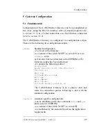
Page 22: ...t refer to section 5 1 Ethernet Internet settings IP address of the CAN Ethernet Gateway 192 168 10 111 Subnet Mask 255 255 255 0 Standard Gateway 192 168 10 1 one UDP2 server one TCP server CAN settings CAN bit rate 1 Mbit s CAN identifier for error messages 0xFE RS 232 interface Baud rate 9600 baud Data bits 8 Parity none Stop bits 1 Protocol flow control hardware 2 BTP Block Transfer Protocol f...

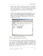
Page 23: ...modem cable to the RS 232 interface of the CAN Ethernet Gateway and a free serial interface on the PC e g COM1 Start a terminal program on the PC the program HyperTerminal will be used for the following examples this program is part of the MS Windows operating system if you use a different terminal program appropriate configuration must be made Set the baud rate and the protocol for the serial int...

Page 24: ... 16 SYS TEC electronic GmbH 2007 L 1032e_9 Figure 5 HyperTerminal Configuration 2 Be sure that you have correctly connected the supply voltage polarity and then turn on the power Figure 6 CAN Ethernet Gateway Start Message ...

Page 25: ...e in non volatile memory EEPROM Predefined files are included for initial configuration These are located on the CD under Products GW 003 SO 1027 RC Files UDP for the UDP transfer or Products GW 003 SO 1027 RC Files TCP for the TCP transfer Each folder contains a file for a server configuration UDP_Server_1CAN txt or TCP_Server_1CAN txt and a file for a client configuration UDP_Client_1CAN txt or ...

Page 26: ...efer to section 4 2 4 for example to 125 kBit s and CAN identifier 0x81 if can0 baud 4 canid 81 on Save the configuration file under a different name for example UdpServer_1CAN_117 txt The generated configuration file is written to the CAN Ethernet Gateway as follows 1 Change to the directory save cd save save 2 Erase the existing configuration file rc save rm rc save sync ...

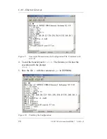
Page 27: ...figuration file rc save write rc After you ve input the command you can send a file to the CAN Ethernet Gateway using the HyperTerminal tool The following images show how to do this Figure 7 Sending a Configuration File via HyperTerminal Figure 8 Selecting a Configuration File ...

Page 28: ..._9 Figure 9 Successful Transmission of a Configuration File Terminate with Crtl D 4 To end the transfer push Ctrl D The Gateway will show the execution with the prompt save 5 Save the file rc with the command sync in EEPROM Figure 10 Finishing the Configuration ...

Page 29: ...nd standard gateway stored in the configuration file all correspond to their settings Now the Gateway is configured and can be accessed over the Ethernet e g Telnet Figure 11 Verifying the Selected Configuration This concludes the initial start up of the device The CAN Ethernet Gateway functions with different interfaces refer to section 4 2 which enable the data exchange over the Ethernet and CAN...

Page 30: ...o enables configuration of remote CAN Ethernet Gateways A condition for this however is the initial configuration of the IP address with the command ipcfg refer to section 4 5 12 Without this initial configuration of the IP address the CAN Ethernet Gateway can only be addressed via its standard configuration refer to section 3 5 1 A Telnet client is already included in the Windows package This Tel...

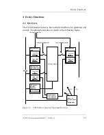
Page 31: ...le CAN Interface can0 Input filter fin Output filter fout UDP Interface udp0 Input filter fin Output filter fout UDP Interface udp1 optional Input filter fin Output filter fout Ethernet CAN Command mkif rm Command btp0 on off Commandcan0 on off UDP Server Interface udpserv0 Port number LED Interface UDP red green CAN red green Telnet or RS 232 Access for Configuration CAN Server UDP Figure 12 CAN ...

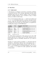
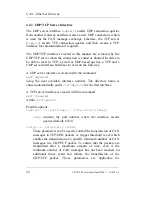
Page 32: ...ernet Available Interfaces Type Maximum amount Requirements CAN can 1 required mandatory UDP Client udp 3 required based on application needs UDP Server udpserv 1 required mandatory TCP Client tcp 3 required based on application needs TCP Server tcpserv 1 required mandatory LED led 1 required mandatory Table 6 Interface Overview The UDP interface transports the CAN messages based on the UDP protoc...

Page 33: ...f if name option e g if can0 or also cd if if name option e g if can0 canid 123 After an interface has been created the current settings can be queried by entering the command interface name number e g if can0 Usage if can0 on off canid hex baud num bus num buf num Current settings on canid 0xF6 baud 0 1MBit s bus 0 state 0x0 ...

Page 34: ...is created with the command mkif udpserv using the next available interface number The directory name is chosen automatically and is if udpserv0 for the first interface A TCP server interface is created with the command mkif tcpserv within if tcpserv0 Possible options option port num trig cnt time num contains the port number where the interface awaits queries default 8234 trig trig cnt time These...

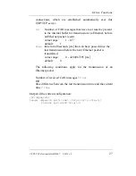
Page 35: ...range 1 127 default 1 time time in milliseconds ms that can have passed since the last transmission before the next Ethernet packet is transmitted value range 0 4294967295 ms default 0 The following conditions apply for the transmission of an Ethernet packet Number of received CAN messages cnt OR time difference between the last transmission time and the current time time Output of the current con...

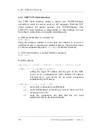
Page 36: ...ber It is used to establish an active connection to another Gateway The directory name is selected automatically and is if udp0 for the first interface A TCP client interface is created with the command mkif tcp 0 Possible options option addr switch alive reco trig addr to ipaddr port setting the target IP address and the port of the UDP server to be communicated with default IP address 192 168 10...

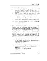
Page 37: ...of CAN telegrams within TCP UPD packets A trigger threshold is set which enables a specified minimum number of CAN messages to be transmitted in a single UDP TCP packet In order to make sure that the packets are transmitted after a maximum time even if the minimum number of CAN telegrams has not be reached an additional timer event can initiate the transmission of the UDP TCP packets These paramet...

Page 38: ...telegrams cnt OR time difference between the last transmission time and the current time time Output of the current configuration if udp0 Usage udp0 to ipaddr port on auto off alive num reco num time trig cnt time 0 frames sent 0 frames recv d state Connection establishment in process Current settings to 192 168 10 118 8234 alive 1 reco 1 120 trig 1 0 ...

Page 39: ...d switch on off on initializes the CAN driver off switches off the CAN driver default baudidx baud num sets the transfer rate corresponding to the baudrate index according to CiA DSP3053 0 1 MBit s default 1 800 kBit s 2 500 kBit s 3 250 kBit s 4 125 kBit s 5 100 kBit s 6 50 kBit s 7 20 kBit s 8 10 kBit s canid canid hex Sets the CAN identifier hex which is used when error messages are sent defaul...

Page 40: ...he CAN bus connection that is to be used for the interface default 0 GW 003 supports a CAN Bus num 0 in preparation GW 003 2 CAN Ethernet Gateway with two CAN bus interfaces value range 0 num 1 bufid buf num num determines the number of CAN messages that are stored upon receipt and transmission default 100 The setting becomes active when the interface is switched on and effects the high as well as...

Page 41: ...for the interface It is possible to select which LEDs go with which interface using the adjustable filter defines refer to section 4 3 Example With the setting if led0 fin hd1 ld23 the states of interface 1 are assigned to the LEDs for CAN error and CAN traffic identified by hd and the states of interface 2 and interface 3 are displayed on the BTP error and BTP connection LEDs The states of other ...

Page 42: ...N identifiers CAN IDs are passed on Furthermore individual CAN identifiers can be selected for highly specific filtering schemes The filter rules can be determined by calling an interface s filter files If no filter rules are present then all messages are passed on 4 3 2 Input Filter The input filter determines which messages will be accepted by the interface input fin For example with a CAN inter...

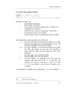
Page 43: ...identifier as hexadecimal number for which the filter rule applies If no CAN identifier is given the filter rule can apply for any CAN identifier idh last CAN identifier as hexadecimal number for which this filter rule applies If only one CAN identifier is given then the filter rule only applies for this CAN identifier r this rule applies for CAN RTR4 frames d this rule applies for CAN data frames...

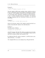
Page 44: ...from the CAN Ethernet Gateway are sent with low priority Example 2 if can0 fin ld 400 400 ld 2c0 2c0 Only CAN messages with the CAN identifiers 0x400 and 0x2C0 are passed on from the CAN interface to the other interfaces Example 3 File rules can be combined if can0 fin ld 180 57F if can0 fin ld 700 700 All CAN messages from the CAN interface are passed on to the other interfaces with the exception...

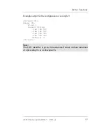
Page 45: ...le output for the configuration of example 3 if can0 fin Usage fin if id 1 Current filter lds 180 57f lde 180 57f lds 700 700 lde 700 700 default l if can0 Note The CAN identifier is given in hexadecimal format without indication of a preceding 0x or a subsequent h ...

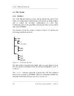
Page 46: ...volatile data in an EEPROM The structure of the file system is shown in Figure 13 and has the following predefined structure Figure 13 File System Structure The file system is located in the RAM After a power failure or reset the file system is initialized with the default configuration refer to section 5 The save directory represents a special case All files contained therein can be stored in EEP...

Page 47: ...store files in the EEPROM the process must be started manually by the user with a call of the sync command refer to section 4 5 8 The files in the save directory can be modified by the user The most important file in this directory is the configuration script rc This file is executed when the firmware is started under the condition that the switch DEFT OFF and contains all of the configuration dat...

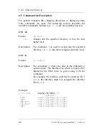
Page 48: ...sed to switch into the specified directory dir or into the next higher directory level 4 5 2 ls Format ls dir Description The command ls shows the files of the indicated or current folder The interface ID which is required for displaying the filter rules is given along with the command See example the interface can0 has the interface ID 1 id 1 the interface udp0 was assigned the interface ID 4 id ...

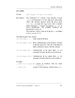
Page 49: ...n 4 2 The interface can be removed using the rm command refer to section 4 5 5 The following files are created if if name Link to parent directory if if name conf Static configuration of the interface format is interface specific This file is intended for future expansions and is currently unused if if name fin Configuration of the input filter i e for messages from the interface to the Gateway if...

Page 50: ...at sufficient memory resources are available The following memory areas are available Eeprm data in EEPROM for non volatile storage of files lwIP internal memory of the TCP IP stack SysSt system stack UsrSt user stack Gcm gateway application Example mem Free file handles 40 Memory total free max blocks Eeprm 2026 1668 1442 2 lwIP 8192 8090 8090 1 SysSt 2410 2148 1908 2 UsrSt 9000 7058 6658 2 Gcm 1...

Page 51: ... rm in the save directory Example rm save rc deletes the configuration file rc in the save directory sync writes save directory into EEPROM 4 5 6 write Format write fname Description With the command write an ASCII file is created and given the name fname If an existing file is to be modified this should be indicated with cat a file is deleted with rm and modified accordingly via the intermediate ...

Page 52: ...d configuration file cat stdrc siocfg 9600 ipcfg 192 168 10 111 255 255 255 0 192 168 10 1 mkif led if led0 fin l hd1 mkif can mkif udpserv mkif tcpserv if can0 baud 0 canid fe on 4 5 8 sync Format sync Description The sync command writes files located in the save directory that are not yet saved into the EEPROM Thus the files are available again following power on or a reset refer to section 4 4 ...

Page 53: ...0 0x0E 0xD3 4 5 10 exit Format exit Description The exit command terminates an on going Telnet session The same can be achieved by entering Crtl D 4 5 11 reset Format reset Description The reset command resets the CAN Ethernet Gateway software reset Depending on the DEFT DIP switch position the corresponding configuration script will be loaded 5 MAC Media Access Control Unique Ethernet address for...

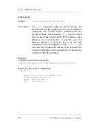
Page 54: ... Telnet and the BTP interface since otherwise no communication is possible over the Ethernet interface It therefore has to be the first command in the configuration script save rc and must also have a unique IP address in the network The current configuration can be displayed by entering the command without parameters Example Configuring the device parameters ipcfg 192 168 10 117 255 255 255 0 192...

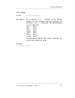
Page 55: ...siocfg switches on the RS 232 interface for the command input and configures the baud rate Baudrate being used The following baud rates are supported 4800 Baud 9600 Baud 19200 Baud 38400 Baud 57600 Baud 115000 Baud The parameters hardware flow control 8 data bits one stop bit and no parity are preset Example siocfg 57600 ...

Page 56: ...CAN Ethernet Gateway 48 SYS TEC electronic GmbH 2007 L 1032e_9 ...

Page 57: ...executed if the switch DEFT is set to ON or if no save rc exists or if an error has been detected in the EEPROM or if a firmware update has been performed it contains the following entries siocfg 9600 ipcfg 192 168 10 111 255 255 255 0 192 168 10 1 mkif led if led0 fin l hd1 mkif can mkif udpserv mkif tcpserv if can0 baud 0 canid fe on The CAN Ethernet Gateway is in a passive state and waits for c...

Page 58: ...ies of commands and parameters as used in the example file rc siocfg 9600 Switching on the RS 232 interface and setting the baud rate ipcfg 192 168 10 117 255 255 255 0 192 168 10 1 Setting the IP address subnet mask and standard Gateway mkif led Creating the LED interface for status display if led0 fin l hd1 Configuration of the LED interface mkif can Creating a CAN interface mkif udp Creating a ...

Page 59: ...he specific requirements Before writing the configuration back to the device the file save rc must be deleted rm rc With write rc the input of the configuration is started It is transferred to the Gateway by being marked in the editor and then copied to the terminal window The input of the command write is finalized with Crtl D key combination Using the command cat rc the configuration can be chec...

Page 60: ... not deleted As an alternative access over the RS 232 interface is possible whereby access to the CAN Ethernet Gateway occurs independently of the IP address 5 5 Assigning Passwords There is also the possibility of creating a password for access via Telnet and RS 232 To do this the file passwd located in the save directory is used The contents of this file corresponds to the password The file is c...

Page 61: ...AN message loss Possible causes CAN bus load too high receive buffer too small refer to section 4 2 4 for settings Indication on Gateway CAN Error LED illuminates briefly Problem CAN TxBuffer overflow Possible causes CAN messages are being incorporated too quickly into the CAN send buffer for example due to high bus load and low priority of the CAN ID to be sent General incorporation of error mess...

Page 62: ...ateway Ethernet error LED illuminates Problem Error during receipt or transmission via BTP Possible causes e g if the recipient does not have a free buffer or in the event of a timeout General CANtoTCP IP send buffer is discarded message loss Indication on Gateway Ethernet error LED illuminates CAN bus off error Possible causes incorrect CAN bus cabling wrong CAN bitrate hardware error Gateway CAN...

Page 63: ...ge was successful Ethernet Error LED CAN Error LED Error Description illuminates No connection established via BTP interface or connection interrupted illuminates BTP send buffer overflow message loss illuminates BTP receive buffer overflow message loss illuminates Error while sending or receiving over BTP message loss short flashes Receive buffer overflow message loss blinks with 50 50 on off rat...

Page 64: ...sage with identifier 0xFE is enabled The format of the error message is specified as follows Byte 0 1 2 3 4 5 6 7 Contents Emergency Code Error Register Interface Number Error Code reserved reserved Table 8 Structure of a CAN Emergency Message The emergency code can assume the following values 0x1000 if a new common error has occurred 0x8140 node comes out of CAN bus off state 0x0000 the device wo...

Page 65: ...tion has been terminated 0x2000 generic CAN controller error internal hardware error of the Infineon TwinCAN bit stuffing error form error CRC error These device error states can also be queried via Telnet or RS 232 The state state is located in the CAN interface Along with the possible error states the following additional bits provide information about the existing BTP connections 0x0200 The int...

Page 66: ...CAN Ethernet Gateway 58 SYS TEC electronic GmbH 2007 L 1032e_9 ...

Page 67: ...red The corresponding setup program can be found on the included CD in the SO 1027 folder Start the setup program on the CD and follow the instructions that appear on the screen The program will be installed in the following folder C Programs SYSTEC electronic CAN ETHERNETmodul_Utility_Disk The installation path can be changed by the user as desired Note Be sure that you have administrator rights ...

Page 68: ...ill find the header file for the EthCAN Dll which contains all prototypes for the public functions of the DLL as well as all data structures and data types used This header file needs to be included in the development project along with the DLL for writing user applications The folder Doku contains the Systems Manual for the CAN Ethernet Gateway as a PDF file The folder Demo Prj contains a demo pr...

Page 69: ...hese functions 7 3 1 The Concept of the EthCan Dll With the EthCan Dll up to 5 CAN Ethernet Gateways can be addressed simultaneously within an application Furthermore it is also possible to access 5 CAN Ethernet Gateways from a remote application as long as they have the same remote address as shown in application 1 This is because multiple interfaces can be connected to the CAN Ethernet Gateway a...

Page 70: ...0 Available Functions within the Software States If multiple CAN Ethernet Gateways are used in an application then these states apply to each CAN Ethernet Gateway While the first CAN Ethernet Gateway is already in the DLL_INIT state the second Gateway can be in the HW_INIT state 7 3 2 EthCan Dll Function Interface This section describes the interface functions of the CAN Ethernet DLL in terms of t...

Page 71: ...n value is the software version number in DWORD format It is structured as follows bit 0 7 most significant portion of version number in binary format bit 8 15 least significant portion of version number in binary format bit 16 31 release version number in binary format Application Example DWORD dwVersion char szVersion 16 Get version number dwVersion EthCanGetVersion convert to a string wsprintf ...

Page 72: ...he so called Blocked Mode if a NULL pointer is given as the pointer for the callback function parameter 3 The function will only return if a successful connection to the CAN Ethernet Gateway was established or if an error has occurred e g in the form of a timeout 2 The function operates in the so called Non blocked Mode if a valid address has been sent to a callback function The function initializ...

Page 73: ...IpAddress IP address WORD m_wPort Port number tUsedProtocol m_UsedProtocol Protocol UDP or TCP DWORD m_dwReconnectTimeout Timeout for Reconnect DWORD m_dwConnectTimeout Timeout for Connect DWORD m_dwDisconnectTimeout Timeout for Disconnect tEthCanHwParam Figure 14 Hardware Parameter Structure Overview This structure has to be filled out accordingly prior to a return to the function The IP address ...

Page 74: ...he Callback function for the connection status of the CAN Ethernet Gateway This value can be NULL when it is passed to the Init function which means that there is no Callback function If a Callback function is to be used to react to changes in the connection status the following declaration has to be made void PUBLIC EthCanConnectControlFct tEthCanHandle EthCanHandle_p DWORD dwConnectionState_p It...

Page 75: ...ll of the Callback function This could be the address of an instance of the CAN Ethernet Gateway if multiple connections are managed within an instance table are to be addressed If only one Callback function was declared for multiple instances then the argument pointer and its access to the elements in the instance table can be used to determine which instance the Callback function was called from...

Page 76: ...nectTimeout 5000 5s without Callback Function initialize a CAN Ethernet Gateway without a Callback function dwRetcode EthCanInitHardware EthCanHandle EthCanHwParam NULL NULL with Callback Function void PUBLIC EthCanConnectControlFct tEthCanHandle EthCanHandle_p DWORD dwConnectionState_p void pArg_p switch dwConnectionState_p Connection in process case kConnecting break Connection Established case ...

Page 77: ...sk of this function is to break an existing connection in a controlled manner and then de initialize the data structures of the instance The return parameter EthCanHandle_p describes the instance that is to be disconnected 1 In Blocked Mode the connection process gets started and waits for the completion of the connection process The function returns when the connection has been disconnected or if...

Page 78: ...nitHardware was called previously and returned without error If the functions were called in Non blocked Mode it is important to be sure in any case that before ending the application the disconnect has been signaled via the Callback function Application Example Both application examples below show the use of the function with a blocking and non blocking call Blocking call define IP_ADDR 192 0 168...

Page 79: ...d PUBLIC EthCanConnectControlFct tEthCanHandle EthCanHandle_p DWORD dwConnectionState_p void pArg_p switch dwConnectionState_p case kEstablished EthCanInst_g EthCanHandle_p fConnected TRUE break case kConnecting case kClosing case kClosed EthCanInst_g EthCanHandle_p m_fConnected FALSE break void main void DWORD dwRetcode tEthCanHandle EthCanHandle initialize a CAN Ethernet Gateway with callback fu...

Page 80: ...ronic GmbH 2007 L 1032e_9 if dwRetcode ETHCAN_SUCCESSFUL printf n Successfully closed n Wait for the disconnect signalized by the Callback function do Sleep 10 while EthCanInst_g EthCanHandle m_fConnected Exit application return dwRetcode ...

Page 81: ...ANERR_QRCVEMPTY Parameter EthCanHandle_p Instance Handle of the CAN Ethernet Gateway pRcvCanMsg_p Address to a CAN message structure This address must not be NULL The structure of the CAN message is as follows typedef struct DWORD m_dwID CAN Identifier BYTE m_bMsgType CAN Frame Format BYTE m_bLen CAN data length BYTE m_bData 8 CAN Data max 8 Bytes tCANMsg Figure 17 CAN Message Structure When forma...

Page 82: ...nto the CAN message structure pRcvTime_p Address to a Timestamp structure of a CAN message This address must not be NULL The Timestamp structure is defined as follows typedef struct DWORD m_dwMilliSec Milliseconds WORD m_wMilliSec_Overflow Milliseconds overflow WORD m_wMicroSec Microseconds tCANTimestamp Figure 18 The CAN timestamp structure The member variable m_dwMilliSec contains the number of ...

Page 83: ... ETHCAN_CANERR_QRCVEMPTY ETHCAN_CANERR_QOVERRUN Application Example tEthCanHandle EthCanHandle tCANMsg RecvCanMsg tCANTimestamp RecvTime DWORD dwRetcode Read CAN message dwRetcode EthCanReadCanMsg EthCanHandle RecvCanMsg RecvTime if dwRetcode ETHCAN_SUCCESSFUL CAN message received else if dwRetcode ETHCAN_CANERR_ QRCVEMPTY no CAN message in the message buffer else error during receipt of the CAN m...

Page 84: ...ans that a buffer overflow occurred Parameter EthCanHandle_p Instance handle of the CAN Ethernet Gateway pSendCanMsg_p Address to a CAN message structure This address must not be NULL pSendTime_p Address to a Timestamp structure This address must not be NULL The parameter pSendCanMsg_p corresponds to an address pointing to the structure of a CAN message as explained for the function EthCanReadCanM...

Page 85: ...lication Example tEthCanHandle EthCanHandle tCANMsg CanMsg tCANTimestamp SendTime DWORD dwRetcode Initialization of a Standard RTR Frame CanMsg m_dwId 0x180 CAN ID CanMsg m_bMsgType ETHCAN_MSGTYPE_STANDARD ETHCAN_MSGTYPE_RTR CanMsg m_bLen 8 8 Byte requested Data length SendTime m_dwMillis 0 Send CAN message dwRetcode EthCanWriteCanMsg EthCanHandle CanMsg SendTime if dwRetcode ETHCAN_SUCCESSFUL CAN...

Page 86: ... Ethernet and can be called up with the help of this function In addition to the CAN status the current connection status of the Ethernet connection between the PC and the CAN Ethernet Gateway is also returned This function should be called in specific time intervals in order to be able to react to potential CAN errors Parameter EthCanHandle_p Instance Handle of the CAN Ethernet Gateway pStatus_p ...

Page 87: ..._ERR_ILLPARAM ETHCAN_ERR_HWNOINIT ETHCAN_ERR_HWNOTCONNECTED Application Example tEthCanHandle EthCanHandle tStatus Status DWORD dwRetcode read CAN Status dwRetcode EthCanGetStatus EthCanHandle Status if dwRetcode ETHCAN_SUCCESSFUL if Status m_wCanStatus ETHCAN_CANERR_OVERRUN Overrun error occurred else Error while reading the CAN status ...

Page 88: ...rrent connection status of the CAN Ethernet Gateway If there was no callback function declared upon initialization of the Gateway then this function can be used to call up the connection status with a polling procedure This function should be used if the initialization and de initialization routines have been called in Blocked Mode The parameter pState_p returns the current connection status after...

Page 89: ...tConnectionState ConnectionState DWORD dwRetcode Read Connection Status dwRetcode EthCanGetStatus EthCanHandle ConnectionState if dwRetcode ETHCAN_SUCCESSFUL if ConnectionState kConnecting Code to be executed if ConnectionState kEstablished Code to be executed else Error while reading the connection status ...

Page 90: ... interference on the CAN Bus The parameter dwResetCode_p is used to determine whether the send and receive buffer in the DLL as well as the send and receive buffer of the CAN Ethernet Gateway and its CAN interface CAN controller should be reset The following parameter values can be given for the reset code Erase the send buffer for CAN messages in the DLL define RESET_TRANSMIT_QUEUE 0x00 Erase the...

Page 91: ...ed Return Values see Section 7 3 3 ETHCAN_SUCCESSFUL ETHCAN_ERR_ILLHANDLE ETHCAN_ERR_ILLPARAM ETHCAN_ERR_HWNOINIT ETHCAN_ERR_HWNOTCONNECTED Application Example tEthCanHandle EthCanHandle DWORD dwResetCode DWORD dwRetcode Reset all buffers and reset the CAN interface of the CAN Ethernet Gateway dwResetCode RESET_ALL_QUEUES RESET_CAN_CONTROLLER Reset the CAN interface dwRetcode EthCanResetCan EthCan...

Page 92: ...0x2 ETHCAN_ERR_ILLHANDLE 0x3 ETHCAN_ERR_HWNOINIT 0x4 ETHCAN_ERR_HWINUSE 0x5 ETHCAN_ERR_HWNOTCONNECTED 0x6 ETHCAN_ERR_HWCONNECT_FAILED 0x7 ETHCAN_ERR_HWDISCONNECT_FAILED 0x8 ETHCAN_ERR_MAXMODULES 0x9 ETHCAN_ERR_SAL 0xA ETHCAN_ERR_IFBTP 0xB ETHCAN_ERR_RESOURCE 0xC Table 11 EthCan Dll Interface Function Error Codes ETHCAN_SUCCESSFUL The function was executed without errors ETHCAN_ERR_ILLPARAM An ille...

Page 93: ...dle for which the initialization routine was already called and returned successfully In order to perform a new initialization with modified parameter values the de initialization function EthCanDeinitHardware has to be called before a new initialization can occur ETHCAN_ERR_HWNOTCONNECTED The function was called but at the time of the call there was no connection of the CAN Ethernet Gateway to th...

Page 94: ...ether the assigned parameters such as IP address and port number are correct and that the remote address really is accessible over the Ethernet connection ETHCAN_ERR_HWDISCONNECT_FAILED This error code is returned by the function EthCanDeinitHardware only if it was called in blocking mode The cause of this is that the disconnection to the remote address could not be closed within the timeout time ...

Page 95: ...sources or an unsupported version of the Windows socket interface The call of the WIN32 functions for the Windows socket interface such as Connect Bind Accept Send and Recv returned an error due to invalid parameters ETHCAN_ERR_IFBTP An error occurred during the initialization or de initialization of the BTP interface Block Transfer Protocol for UDP or TCP ETHCAN_ERR_RESOURCE A resource could not ...

Page 96: ...x0001 ETHCAN_CANERR_OVERRUN 0x0002 ETHCAN_CANERR_BUSLIGHT 0x0004 ETHCAN_CANERR_BUSHEAVY 0x0008 ETHCAN_CANERR_BUSOFF 0x0010 ETHCAN_CANERR_QRCVEMPTY 0x0020 ETHCAN_CANERR_QOVERRUN 0x0040 ETHCAN_CANERR_QXMTFULL 0x0080 ETHCAN_CANERR_REGTEST 0x0100 ETHCAN_CANERR_MEMTEST 0x0200 Table 12 CAN Error Codes ETHCAN_CANERR_OK No CAN Error has occurred ETHCAN_CANERR_XMTFULL The send buffer in the CAN Controller ...

Page 97: ...AN Bus ETHCAN_CANERR_QRCVEMPTY The receiving queue for CAN messages within the DLL does not contain any CAN messages which means that all CAN messages have been read or no new CAN messages have been received ETHCAN_CANERR_QOVERRUN Overflow of the receive queue for CAN messages It is possible that some CAN messages will have been lost ETHCAN_CANERR_QXMTFULL Overflow of the send queue for CAN messag...

Page 98: ...d with the function GetProcAddress The demo program is based on a WIN32 console application and is limited to the support of a CAN Ethernet Gateway instance After the program has been started and the EthCan Dll has been loaded a connection to a CAN Ethernet Gateway addressed by IP address and Port number will be established If the connection was established successfully then a CAN message will be ...

Page 99: ...o program is started as follows Open a command shell and switch to the folder of the executable file EthCanDemo exe which was given during installation To start the demo program enter the name of the executable program when given the input prompt followed by the IP address the Port number and the desired transfer protocol The following shows two examples Example 1 Release EthCanDemo exe 192 168 01...

Page 100: ...CAN Ethernet Gateway 92 SYS TEC electronic GmbH 2007 L 1032e_9 ...

Page 101: ...ments must be met in order to proceed with the firmware update 1 Windows OS based PC with the MemTool software installed and at least one free serial port COM port 2 A Nullmodem cable to connect the CAN Ethernet Gateway to the PC 8 1 Preparations Proceed with the following steps to prepare the firmware update 1 Power on the device 2 Connect the serial interface on the CAN Ethernet Gateway with a f...

Page 102: ...Ethernet Gateway 1 Go to menu Target Change and select the controller SAB XC161CJ XC164CS XC167CI 16FF STEP AC 2 Next the serial communication interface needs to be configured Therefore go to menu Target Setup Communication Port A configuration dialog window appears where you can configure the serial interface used for firmware update 3 Connect to the target using the Connect button After the conn...

Page 103: ...a menu File Open File 6 Select all sectors from the right side list see Figure 22 and assign them to the memory sectors on the left side of the application window by using the Add Sel button Figure 22 Memory areas and sector assignment 7 Click button Program to start the program download 8 After successfully downloading the firmware set the boot switch to Off and reset the device by reset button o...

Page 104: ...a newer version number the resource files on the EEPROM will be discarded With restarting the device after firmware update the standard configuration with default IP 192 168 10 111 and the settings described in the standard RC file is loaded The user specific configuration must be downloaded afterwards ...

Page 105: ...ts 5 DeviceNet 1 Dimensions 7 DIN EN Rail Assembly 7 Driver Installation 59 Dynamic Linked Library 61 EEPROM 39 Error Codes 84 Error Message 2 EthCan Dll 60 76 Concept 61 EthCan Dll Function Interface 62 EthCan Lib 61 EthCanDeinitHardware 69 86 EthCanGetConnectionState 80 85 EthCanGetStatus 78 EthCanGetVersion 63 EthCanInitHardware 64 86 EthCanReadCanMsg 73 EthCanResetCan 82 EthCanWriteCanMsg 76 E...

Page 106: ...47 save 38 39 SDS 1 siocfg 47 Standard CAN Frame 73 Standard Gateway 21 46 Standard Resource File 96 Subnet Mask 18 21 46 Supply Voltage 7 9 Switches 13 sync 44 TCP 14 26 28 TCP Client 28 TCP Server 26 TCP IP 2 28 TCP_Client_1CAN txt 17 TCP_Server_1CAN txt 17 Technical Data 7 Telnet 1 7 21 22 Transfer Rate 31 UART 1 UDP 14 26 28 UDP Client 28 UDP Server 26 UDP IP 2 28 UDP TCP Client 28 UDP TCP Ser...

Page 107: ...Ethernet Gateway Document number L 1032e_9 April 2007 How would you improve this manual Did you find any mistakes in this manual page Submitted by Customer number Name Company Address Return to SYS TEC electronic GmbH August Bebel Str 29 D 07973 Greiz Germany Fax 49 0 3661 6279 99 ...

Page 108: ...Published by SYS TEC electronic GmbH 2007 Ordering No L 1032e_9 Printed in Germany ...

Reviews: