3
2. C/CS Back focus Adjust Ring
– Allows the user to adjust the back
focal length or picture focus by rotating this ring clockwise for C-
mount and
counter-clockwise for CS-mount lenses.
3. Mounting Bracket Hole
– This threaded ¼"-20 hole is used to
mount the camera onto a mounting bracket or tripod.
4. Iris Adjustment Pot (Potentiometer)
– This control allows the user
to adjust the level of the auto iris when the A/I lens selection switch
is set to DC and a DC lens is mounted on the camera. The switch
should be in the video position when an auto iris video lens is
mounted on the camera. If a video auto-iris lens is used, this control
has no function.
5. Phase
Adjustment
– This is used in a multi-camera system when
power is supplied from different sources, causing the camera to be
out of phase. This situation affects auto-switching of the cameras by
causing a vertical flip or roll during the switch interval. The vertical
phase adjustment allows the camera’s line lock sync to be adjusted
from 0 to 360 degrees with reference to zero line crossing of the AC
power source. Ensure that all cameras are powered from the same
electrical source and wired in a similar fashion. Adjust the phase
control on the back of the camera until there is no vertical flip or roll
on the monitor while using an auto switcher.
6. Power
LED
– This green LED illuminates while power is supplied to
the camera.
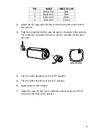
7. Auto-iris Lens Connector
– This four-pin female connector
supplies the power and either video signal or DC control signal to
the auto-iris lens.
8. Function
Switches
– This compartment houses switches for
camera operation. A switch is in the ON position if it is positioned
toward the front of the camera. If the position is set toward the back
of the camera, the switch is OFF. The switches include:
Continued on next page
•
SHTR Switch (Aes/Mes)
– This switch allows the user to choose
between auto exposure and manual exposure. Position the
switch toward the front of the camera for auto exposure, whereby


