background image

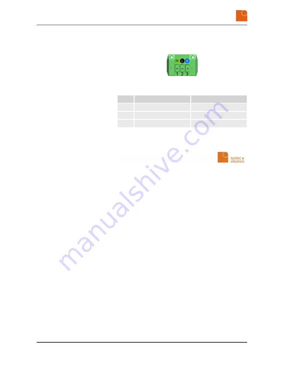
Power is supplied via a 3-pole Phoenix socket of type DFK-PC /3-

GF-7,62. The corresponding plug carries the designation Phoenix Con-

tact PC 4/ 3-ST-7,62.

Fig. 18: 3-pole Phoenix Contact socket for the power supply

Pin

Designation

Significance

1

PE

Surge protectors

2

L

Phase

3

N

Neutral conductor

3.6  Conformity

Systec & Solutions GmbH
CONTROL 217-218-219-221-224-232
Industrial PC/Monitor

n

PURPOSE
For the above product, in the version with a 12 – 24 V DC power

supply, we hereby confirm that it complies with the essential pro-

tection requirements of the EMC Directive 2014/30/EU (formerly

2004/108/EC) (electromagnetic compatibility).
The above product, in the version with a 100 – 240 V AC power

supply, also complies with the requirements of the EC Low Voltage

Directive 2014/35/EU (formerly 2006/95/EC).

n

SCOPE
The product listed above fulfills the requirements of the EMC Direc-

tive 2014/30/EU (formerly 2004/108/EC) on the basis of the fol-

lowing standards:
– EN 61000-6-2:2005
– EN 61000-4-2:2007

The product listed above fulfills the requirements of the Directive

2006/95/EC on the basis of the following standard:
– EN 60950-1:2006

n

CERTIFICATE
Compliance with protection requirements was established with the

housing closed on all sides.

Systec & Solutions GmbH
Emmy-Noether-Straße 17
D–76131 Karlsruhe

Power supply in the low-voltage

range (100 – 240 V AC, 50 – 60 Hz)

Declaration of Conformity

Product description

Conformity

CONTROL 217 PC - Industrial PC


 20

Summary of Contents for CONTROL 217 PC

Page 1: ...CONTROL 217 PC INDUSTRIAL PC INSTRUCTIONS FOR USE CONTROL Read the instructions prior to performing any task ...

Page 2: ...utions GmbH Emmy Noether Straße 17 D 76131 Karlsruhe Telephone 0721 6644 400 Fax 0721 6644 444 email talk systec solutions com Internet www systec solutions com CONTROL 1 en_US 11 11 2015 CONTROL 217 PC Industrial PC 2 ...

Page 3: ...3 6 Conformity 20 4 Starting up 23 4 1 Unpacking the device 23 4 2 Setting up the device 23 4 3 Mounting the device 24 5 Operation 27 5 1 Switching the device on 27 5 2 Switching the device off 27 5 3 Operating the touchscreen 27 5 4 Cleaning the device 28 5 5 Using the optional USB connection 31 5 6 Setting up the WLAN optional 31 5 7 Hard disk LED optional 32 6 Repairs 33 7 Storage 35 7 1 Unmoun...

Page 4: ...Table of contents CONTROL 217 PC Industrial PC 4 ...

Page 5: ... other hints by e mail phone or fax This will help us to ensure that our documentation is as intelligible and user friendly as possible You will find our contact information on the inside of the front cover or under Site information Ä Chapter 10 Site information on page 41 1 2 Copyright notice This user guide is protected by copyright Other than for internal purposes making this user guide availab...

Page 6: ...General information Copyright notice CONTROL 217 PC Industrial PC 6 ...

Page 7: ...as and applications that are subject to vibration and impacts n for carrying out safety functions such as air traffic control flight control systems monitoring controlling nuclear reactions monitoring controlling mass transportation facilities monitoring controlling medical systems monitoring controlling weapons systems Contravening these instructions voids all warranties and manufac turer s respo...

Page 8: ... or moderate inju ries NOTICE This signals a hazard for material property Failure to comply with these instructions may cause material damage This signals useful hints within a series of work processes 2 3 Important safety notes WARNING Risk of injury from electric shock Assembling and connecting plug connectors while voltage is connected may lead to life threatening injuries All work on the devic...

Page 9: ...zard if the device is connected to the mains supply incorrectly Connecting the device incorrectly to the mains supply may expose people to injuries from electric shocks Before connecting up the device always disconnect the line from the power supply Before connecting up always check that the lines are at zero voltage NOTICE Danger of material damage from improber use of the mounted keyboard Handli...

Page 10: ...Safety Important safety notes CONTROL 217 PC Industrial PC 10 ...

Page 11: ...addition they guar antee IP65 protection Fig 1 CONTROL 217 PC No Designation Description 1 Display Used to display information 2 On Off button Switches the device on and off Optional USB connection Used to connect a USB stick Hard disk LED optional Flashes when accessing data on the internal HDD disk Fig 2 Rear view of PC The button on the back of the monitor is used to switch the PC ON and OFF HM...

Page 12: ...display Used to reproduce sounds 3 2 Type plate The product designation and identification will be found on the type plate This is always located on the rear of the device and contains the following information Fig 4 Position of type plate Multimedia kit optional Product description Type plate CONTROL 217 PC Industrial PC 12 ...

Page 13: ...3 Technical data for the device System Model CONTROL 217 Variant Industrial PC Housing material Front plate of stainless steel 1 4301 Surface Front surface sanded IP protection factor IP65 on front PC CPU Intel Celeron N2930 1 86 GHz Burst 2 16 GHz quad core Intel Core i3 4010U 1 7 GHz Intel Core i5 4300U 1 9 GHz Turbo 2 9 GHz Intel Core i7 4650U 3 3 GHz RAM 4 GB DDR3 max 16 GB DDR3 Celeron 8 GB P...

Page 14: ...r PCT projected capacitive multi touch Interfaces Standard interfaces 3x RS232 2x USB 3 0 2x USB 2 0 Intel Celeron 1x USB 3 0 5x USB 2 0 1x Ethernet additional interfaces optional Power supply consumption depending on the device variant Extra low voltage power supply 12 24 V DC 10 5 A Protection of supply lead Extra low voltage DC max 10 A the supply lead should be specified Low voltage power supp...

Page 15: ...a W 382 H 215 Mounting cutout See Ä Chapter 3 4 Dimensions on page 15 D 40 optional for DC Front panel W 504 H 337 D 5 Material of front panel Stainless steel 1 4301 Weight Net weight ca 9 kg 3 4 Dimensions 504 383 AA215 337 216 AA215 Fig 6 Dimensions of front of device Product description Dimensions CONTROL 217 PC Industrial PC 15 ...

Page 16: ...2 192 432 153 5 153 5 237 237 138 m i n 2 8 min 436 cut out min 275 cut out Fig 7 Dimensions of back of device max60 Fig 8 Dimensions in side view Product description Dimensions CONTROL 217 PC Industrial PC 16 ...

Page 17: ...onnectors that are located on the underside of the CONTROL 217 PC Fig 10 Overview of the interfaces on the underside 3 5 2 Description of the external connections Your device will not incorporate all of the following connectors see Ä Chapter 3 3 Technical data for the device on page 13 Product description External connections Description of the external connections CONTROL 217 PC Industrial PC 17 ...

Page 18: ...HDMI socket with pinout 15 pole HD D VGA socket for connecting basic computer Fig 14 VGA socket with pinout 4 pole USB socket type A for connecting components n VoIP hardware components and or n touchscreen and or n keyboard Fig 15 USB socket with pinout Serial connection RS 232 DVI port HDMI port VGA port USB connection Product description External connections Description of the external connecti...

Page 19: ...the power rating of your device Power is supplied via a 2 pole Phoenix socket of type DFK PC 2 GF 7 62 The corresponding plug carries the designation Phoenix Con tact PC 4 2 ST 7 62 Fig 17 2 pole Phoenix Contact socket for the power supply Pin Designation Significance 1 Ground GND 0V 2 Power supply Ethernet RJ45 Power supply in the extra low voltage range 12 24V DC Product description External con...

Page 20: ...ibility The above product in the version with a 100 240 V AC power supply also complies with the requirements of the EC Low Voltage Directive 2014 35 EU formerly 2006 95 EC n SCOPE The product listed above fulfills the requirements of the EMC Direc tive 2014 30 EU formerly 2004 108 EC on the basis of the fol lowing standards EN 61000 6 2 2005 EN 61000 4 2 2007 The product listed above fulfills the...

Page 21: ...many Phone 49 721 6634 400 Fax 49 721 6634 444 talk systec solutions com www systec solutions com Karlsruhe December 1 2014 Karl G Linder CEO Product description Conformity CONTROL 217 PC Industrial PC 21 ...

Page 22: ...Product description Conformity CONTROL 217 PC Industrial PC 22 ...

Page 23: ... be possible to guar antee protection from damage or other harmful influ ences 4 2 Setting up the device The device is approved for operation in enclosed premises 1 Prior to initial commissioning n If necessary disinfect the device spray or wipe with disinfec tant refer to the device s chemical resistance dataÄ on page 28 n Slowly acclimatize the device to room temperature 2 In the event of conden...

Page 24: ...If the device is enclosed you should arrange for suitable ventila tion see the illustration 3 The enclosed wall template shows the size of the necessary cutout and the drilling holes You will find an image of the wall template in section Ä Chapter 3 4 Dimensions on page 15 Fig 20 Rear view showing sealing tape red M6 threaded bolts blue and M3 threaded bolts yellow 4 WARNING Danger of injury due t...

Page 25: ... threaded bolts Optionally instead of the M6 threaded bolts the device can be fastened by boring holes in the front panel ð The device is mounted and sealed Protection factor IP65 is guaranteed only if the switch cabinet or control panel is sufficiently rigid the device is properly installed using the supplied nuts and bolts and with a prop erly seated seal Optionally counterbores may be attached ...

Page 26: ...Starting up Mounting the device CONTROL 217 PC Industrial PC 26 ...

Page 27: ...fashion may cause you to lose data and may also damage the components Save your data regularly Always close down the industrial PC in an orderly fashion Close the system down in an orderly fashion ð The system is switched off The system cannot be closed down in an orderly fashion Hold the ON OFF button pressed for about five seconds ð The system is switched off 5 3 Operating the touchscreen With P...

Page 28: ...leaning the device To prevent malfunctions or incorrect data entry due to inadvertent operations Switch the device off before cleaning it see Ä Chapter 5 2 Switching the device off on page 27 NOTICE Damage caused by cleaning Cleaning the device may give rise to material damage Firmly close all screw connections Do not use high pressure or steam cleaning equip ment Do not use any abrasives or hard ...

Page 29: ...cetonitrile Dowandol DRM PM Perchlorethylene Aliphatic hydrocar bons Ferrous chloride FeCl2 Phosphoric acid 10 Alkaline carbonate Ferric chloride FeCl2 Castor oil 10 formic acid Acetic acid 10 Nitric acid 10 Ammonia 10 Ethanol Hydrochloric acid 10 Amyl acetate Ethyl Salt water Ethanol Ethyl acetate Oxygen Ether Varnish Sulfuric acid 10 Ethyl acetate Chlorofluorocarbons Silicone oil Gasoline Formal...

Page 30: ...ral acids Concentrated alkaline solutions High pressure steam above 100 C A number of other substances may give rise to changes in the surface structure This should be examined and evaluated in each case Resistant to 24 hours exposure to household chemicals at 50 C with no visible damage Ariel Gumption Top Job Ajax Jet Dry Grape juice Domestos Coffee Vim Downey Lenor Vortex Fantastic Milk Wisk For...

Page 31: ...49 721 6634 444 talk systec solutions com www systec solutions com 5 5 Using the optional USB connection Unscrew and remove the dummy plug on the front of the CON TROL 217 PC ð The optional USB connection is now accessible When closing the USB connection make sure it is screwed tight otherwise the IP65 protection level can no longer be guaranteed Firmly screw the dummy plug into place on the front...

Page 32: ...7 Hard disk LED optional The hard disk LED flashes when the internal HDD hard disk is accessed This is however possible only for HDD disks Operation Hard disk LED optional CONTROL 217 PC Industrial PC 32 ...

Page 33: ...iately switch it off see Ä Chapter 5 2 Switching the device off on page 27 The device is defective 1 Send an e mail to support systec hardware com or 2 Fill out a support form at http www systec solutions com de hardware support html Repairs CONTROL 217 PC Industrial PC 33 ...

Page 34: ...Repairs CONTROL 217 PC Industrial PC 34 ...

Page 35: ...n working with heavy equipment WARNING Danger of injury from hot surfaces Power transmission and regulatory components become hot in operation and may lead to injuries Allow these components to cool down before you begin dismounting the device NOTICE Danger of material damage from live equipment Working on live equipment may give rise to material damage Before you carry out any work on a device Di...

Page 36: ...requirements n Use the original packaging n Do not apply any localized pressure to the display n Do not store in the open air n Always store in a dry non dusty place n Always shield the equipment from solar radiation n Avoid mechanical vibration and shocks n Avoid cold weather and extreme temperature fluctuations n Pay attention to the information in the Technical data section Ä Chapter 3 3 Techni...

Page 37: ... may damage the device Pay attention to the handling symbols on the trans port packaging Comply with the stated transport requirements see Ä Transport requirements on page 37 When transporting the device you should comply with the following requirements n Always shield the equipment from solar radiation n Avoid mechanical vibration and shocks n Avoid extreme temperature fluctuations n Pay attentio...

Page 38: ...Packaging and transport Transporting the device CONTROL 217 PC Industrial PC 38 ...

Page 39: ...ly of all devices Under our General Terms and Conditions and in fulfill ment of the conditions of the sales agreement the customer under takes to return all equipment to Systec Services GmbH for proper dis posal Do not dispose of the equipment via your local municipal col lection centers Under the WEEE Directive these may be used only for privately used equipment Disposal CONTROL 217 PC Industrial...

Page 40: ...Disposal CONTROL 217 PC Industrial PC 40 ...

Page 41: ... solutions com en hardware support html n Karl G Linder n Andreas König Court of registration Mannheim District Court Registration number HRB 717236 VAT ID no as per 27a Value Added Tax Act n DE 815434969 Systec Solutions GmbH All rights reserved Technical modifications reserved All trademarks and registered trademarks mentioned are the property of their respective owners Authorized representative...

Reviews: