- 18 -
699-41-20.1
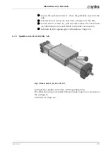
Screw out the cylinder-head screws (1) of the pull-back cap (4). If
a contact flange for inductive proximity switches is attached to the
carriage, dismantle that beforehand.
Shove the pull-back cap (4) to another bearing (7).
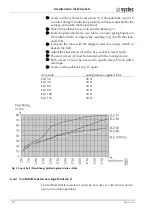
Exert the prescribed force (see table) a tension spring balance in
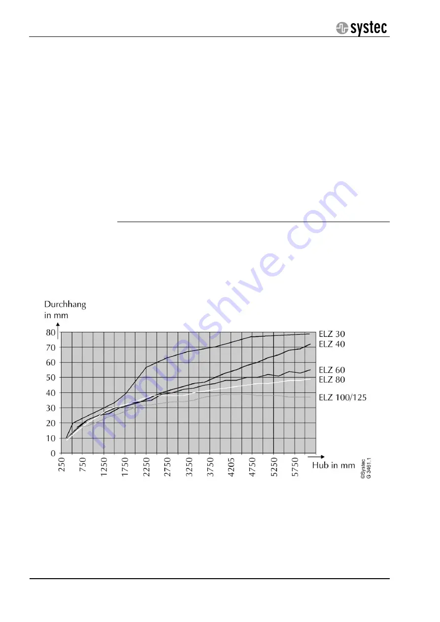
the middle of belt. - Compare the resulting “sag” (f) with the slack-
ened belt.
Compare the value with the diagram, and if necessary stretch or
slacken the belt.
Adjust the stud screws (2) with a hex. socket screw wrench.
The stud screws (2) must be bonded with the locking device.
Both screws (2) must be screwed in equally deep. Check with a
steel tape.
Screw on the pull-back cap (4) again.
Axis-scale
spring balance applied force
ELZ 30
20 N
ELZ 40
20 N
ELZ 60
30 N
ELZ 80
50 N
ELZ 100
50 N
ELZ 125
50 N
Fig. 5 Sag of belt (Durchhang) plotted against stroke (Hub)
6.4.2
Tooth belt tension axis type DuoLine Z
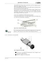
The toothed belt tension is set correctly ex works. A correction is unnec-
essary in normal operation.


