page
6
January 2020 - Rev. 1.2
Order Cod. 1902503003
3. Display and keyboard
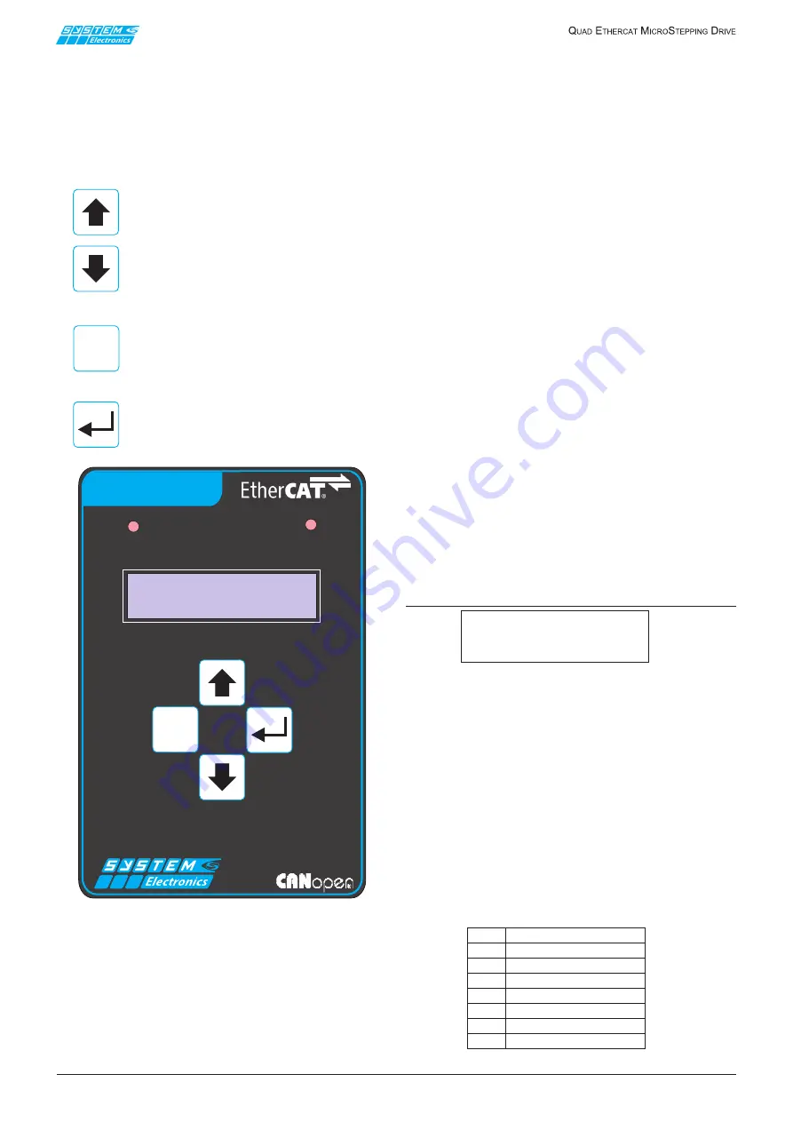
The drive is equipped with a backlit display and a keypad
with four buttons for displaying and editing some of the
operating parameters.
The display is organized as a set of circular sequences
of pages that can be browsed using the buttons on the
keyboard; these are:
To scroll a sequence of pages in the desired
direction or to increase/decrease the value
of a parameter being edited.
To go back to a sequence of pages on an
upper level or to the default page or to
cancel parameter editing operations in
progress.
To switch to a sequence of pages on a
lower level, to access the editing mode for
a parameter that is being displayed and to
confirm its new value.
Figure 3.1
The
main menu
(the sequence of pages at the
highest level) allows to view the following read-only
parameters:
•
Axes status (
default page
)
•
Digital inputs status
•
Digital outputs status
•
Motor supply voltage
•
Motor dissipator temperature
•
Controller temperature and supply voltages
•
Status of jumpers J2..J5 (
for testing only during
drive production
).
Pressing the Enter key while viewing the default page
makes a new sequence of pages appear (
sub-menu
):
•
Axes management firmware release
•
Monitor firmware release
•
Communication mode
(modifiable)
•
EtherCAT node address
(modifiable)
•
CAN network bit rate
(modifiable)
•
CAN network termination and slope resistors
(modifiable)
•
CANopen node address
(modifiable)
•
Ethernet MAC address
•
Ethernet IP address
(modifiable)
•
Ethernet IP subnet mask
(modifiable)
3.1 Display
When the ETC QUAD drive is switched on some messages
appear on the display, showing the operations performed
during the initialization of the axes management
firmware.
If no problems have occurred, after a few seconds the
display shows a message similar to the following:
3.1.1 Axes status page
(default page)
E: 0000 1:01 2:01
Init 3:01 4:01
The beginning of the upper line shows the type of
communication set (E = EtherCAT / C = CANopen) and
the node address (in hexadecimal format).
The EtherCAT node address is set at 0000 to request
dynamic assignment of the address itself. Otherwise the
drive uses the address set as hot-plug address of the
EtherCAT node.
The beginning of the lower line displays (with four
characters) the EtherCAT or CANopen status:
[“Init” / ”PrOp” / ”SfOp” / ” Op “ / “ERR ” / “Boot”].
The status according to standard profile DSP402is then
displayed for each axis 1..4 (in hexadecimal format):
Table 3.1.1.1
ESC
CAN
ETC RUN
ETC QUAD
ESC
01
NotReadyToSwitchOn
02
SwitchOnDisabled
04
ReadyToSwitchOn
08
SwitchedOn
10
OperationEnabled
20
QuickStopActive
40
FaultReactionActive
80
Fault


