background image

page


5

I

ndustrIal

 pC - COpIlOt 15"

O

rder

 C

Ode

 190331

xxxx

M

ay

 2009 - r

ev

. 1.5

It  is  recommended  to  keep  the  UPS  management 

settings as shown below (2 minutes of normal use of 

the terminal before the automatic "soft" shutdown of 

the applications).

System  suspension  and  shutdown  can  be  configured 

following a power cut.

Figure 3.5.1

3.6 Connectivity

The Wireless solutions of the COPILOT allow maximum 

freedom  and  flexibility  of  use  and  allow  remote 

equipment to be piloted.
The COPILOT is a universal operator interface, for the 

possibility to communicate with the machine and receive 

the required data only, as well as the desired manuals 

and easily manage the update of the equipment.
Native interfaces:

• 

2 USB connectors on the rear side.

• 

Ethernet 10/100.

• 

MiniPCI Wi-Fi: wireless radio communication 

according to Standard 802.11b/g at 2.4GHz, with 

point-to-point access or an access point. Possibility 

of encrypting the data for increased WEP security 

at 64 or 128 bit. The maximum distance between 

two communicating units or between the COPILOT 

15" and the access point is 100 m.  

Two internal antennas or one external antenna can 

be installed for applications that require maximum 

performance and radio coverage.

The  FULL  version  of  the  COPILOT  15"  allows  the  full 

capacity of the terminal to be used for OEM applications 

of other services:

• 

Two PC104+ slots (for high performance boards 

on PCI/ISA bus) allow other boards to be used for 

custom applications (CAN, GPS, camera, GPRS, 

modem, additional Ethernet, etc.).

• 

Connection for additional ethernet 10/100 Mbit 

with chipset i82551er.

• 

The optional TV output and audio (Audio LineIN, 

Mic, LineOut) can be requested for multimedia 

applications.

• 

There are 4x24V inputs and 4x24V outputs 250mA 

max non-isolated, protected against short circuits.
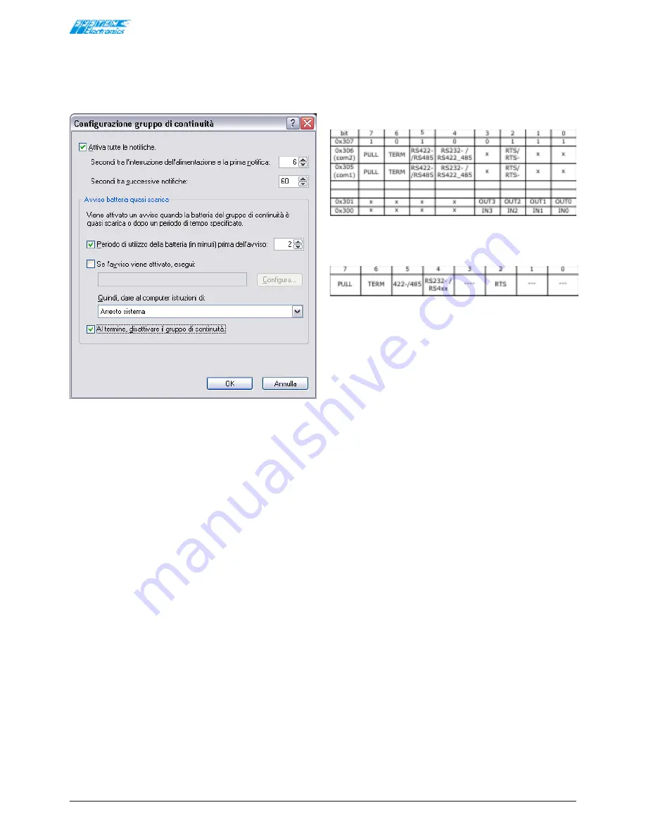
Table 3.6.1

Configuration of the serial ports: (Com1 and Com2).

Table 3.6.2

Bit2:  RTS/RTS-: Selects how to enable the driver in 

transmission for RS422 and RS485 protocols. 

(RTS-) 0: normally not in transmission: 

controlled by the RTS signal. 

(RTS) 1: normally in transmission: controlled by 

the RTS signal. 

Set bit 2 to '1' to use the RS422 serial port as a 

point-to-point always in transmit/receive.

Bit4:  selects between RS232 and 422/485. 

0 must be written on the bit to use the serial 

ports as RS232: and 422/485 is selected by 

setting the value to 1.

Bit5:  selects between RS422 and RS485 (half duplex 

or full-duplex). 

This bit bears no significance for the RS232 

mode. (set to 0). 0 must be written on the bit 

to use the serial ports as RS422: and RS485 is 

selected by setting the value to 1.

Bit6:  termination of the TX+/TX- and RX+/RX- lines. 

This bit is to be set to 0 for the RS232 mode. 

1 must be written on the bit to terminate the 

lines. 120 ohm termination.

Bit7:  PullUp and PullDown of the TX+/TX- and RX-

/RX lines. This bit is to be set to 0 for the 

RS232 mode. 1 must be written on the bit to 

insert the pull-ups on the TX+ and RX+ and 

the pull-downs on the TX- RX- lines. 470Ω 

resistors b5V and towards the GND, 

respectively.

RS232: 0x00
RS422 Multidrop: 0xD0
RS485: 0xF0
RS422 Point-to-Point: 0xD4

The inputs are mapped in I/O at the 0x300 address.

The outputs are mapped in I/O at the 0x301 address.

The HW release can be read at the 0x307 address: 0xA7 

or 0xA5 for the ultra light version.

Summary of Contents for COPILOT 15"

Page 1: ...è íå ÿâëÿþòñÿ îðèãèíàëîì Â ñëó àå ñîìíåíèé èëè ïðîòèâîðå èé â òîëêîâàíèè ñìûñëà Ðóêîâîäñòâà îáðàùàòüñÿ ê âàðèàíòó íà èòàëüÿíñêîì ÿçûêå íà òèòóëüíîé ñòðàíèöå êîòîðîãî èìååòñÿ íàäïèñü ISTRUZIONI ORIGINALI Äàííîå ðóêîâîäñòâî äîñòóïíî íà ñàéòå http extranet system group it stampe esternastampamanuali aspx Instrukcje w nieoryginalnej wersji W razie w tpliwoœci lub sporów co do interpretacji treœci podr...

Page 2: ...d subsequent amendments SYSTEM s p a Div Electronics reserves the right to alter the technical specifications in any way and at any time without prior notice The information in this documentation is deemed to be correct and reliable Any reproduction of this catalogue even partial is only allowed if authorised by SYSTEM s p a Div Electronics DICO is a registered brand by SYSTEM s p a Div Electronic...

Page 3: ...N 4 OUT 24V max 250mA output Galvanic isolation of the serial lines Possibility of software programming the protocol of the serial ports Consumption 35W normal operation 2W in stand by Power supply 21V 28V DC Note A lesser supply allows the terminal to run however the batteries cannot be charged Insufficient supply could cause the terminal to go on when switched off Construction IP67 Connectors M1...

Page 4: ...of the screen does not coincide with the position of the cursor of the mouse Calibration is performed via the Calibration button and then pressing the 4 points indicated on the screen It is recommended to perform the 4 points mode 2 calibration using a pencil for greater precision 3 4 Display The advanced management of the power supply of the Windows screensaver normally includes the automatic shu...

Page 5: ...ional ethernet 10 100 Mbit with chipset i82551er The optional TV output and audio Audio LineIN Mic LineOut can be requested for multimedia applications There are 4x24V inputs and 4x24V outputs 250mA max non isolated protected against short circuits Table 3 6 1 Configuration of the serial ports Com1 and Com2 Table 3 6 2 Bit2 RTS RTS Selects how to enable the driver in transmission for RS422 and RS4...

Page 6: ...on The COPILOT 15 is equipped with an automatic switch on function that is activated when the power supply is connected This function allows the terminal to start automatically when the main power supply is activated to which the COPILOT 15 is connected The terminal does not switch on automatically if switched off manually It must be restarted by pressing the button or disconnecting and reconnecti...

Page 7: ...e Ethernet connector are not used USB 1 5V_USB 2 D 3 D 4 GND_USB CAN 4 CAN_H 5 CAN_L 6 CAN_GND 7 CAN_H 8 CAN_L 9 CAN_GND 24V PNP DIGITAL INPUTS 15 IN_1 16 IN_2 17 IN_3 18 IN_4 19 IN_GND The terminal recognises an active input when a positive supply is connected between the IN and GND 24V PNP DIGITAL OUTPUTS 10 OUT_1 11 OUT_2 12 OUT_3 13 OUT_4 14 OUT_GND The outputs are powered by the 24V main inpu...

Page 8: ...Figure 4 3 1 Rear connectors for 4 holes PWR ETH USB Figure 4 3 2 M12 external connectors 8 holes 24V 2ETH USB 2CAN 1RS232 Figure 4 3 3 M12 external connectors 10 holes Figure 4 3 4 M12 external connectors with I O 10 holes Figure 4 3 5 24V Power Supply M12 Female 5 pole A 1 24V 2 24V 3 GND 4 GND 5 PE Figure 4 3 6 View of the external female connector NOTE The connection of pins 2 and 4 is set up ...

Page 9: ...tor Table 4 3 1 CAN Wiring M12 Male 5 pole A Copilot side male compatible CAN repeater 1 SHIELD 2 3 CAN_GND 4 CAN_H 5 CAN_L Figure 4 3 11 Note The shield is not connected internally It is not recommended to wire the CAN_GND signal but only CAN_H and CAN_L M12 Input and Output Connection 24V PNP Digital Inputs M12 Female 5 pole A Figure 4 3 12 View of the rear connector 1 IN_1 2 IN_2 3 IN_3 4 IN_4 ...

Page 10: ...rom other waste at the end of its life cycle The separate waste collection of this equipment at the end of its life cycle is organised and managed by the manufacturer Any user who wishes to dispose of this equipment must therefore contact the manufacturer and follow the system adopted by the latter for the separate collection of the equipment at the end of its life cycle Adequate separate collecti...

Reviews: