pag.
4
INDUSTRIAL PC - COPILOT 15,6"
Order 2E00xxxx
November 2020 - Rev. 1.2
4. Description and
operation
The PC switches on automatically with the presence of
the input power supply: it may take several seconds
before the start screen appears with the "System" logo.
Copilot 15,6''
has two gigabit-Ethernet networks, two
RS232 serial ports, a PS2 mouse and keyboard port,
and USB 2.0 ports; as an option you can request con-
nections for USB3.0, display port, DVI or external VGA
for a remote monitor, audio connection.
The main operating systems can be pre-installed on the
terminal: Windows 10 Iot, Linux Debian, Windows7 and
Windows 8.1.
After shutdown of the operating system it is possible
to reignite the
Copilot 15,6''
disconnecting for 10
seconds and reconnecting the external 24VDC / 48VDC
power supply or by pressing the optional power button.
Copilot 15,6''
can also be turned on by WakeOn-Lan
commands from an external PC connected to the ter-
minal's Ethernet network.
4.1 Installation in the hanging
version (VESA100)
To correctly mount the
Copilot 15,6''
in the hanging ver-
sion on the VESA100 arm, follow the instructions below:
- Remove the
Copilot 15,6''
from the packaging and
place it on a flat surface free from objects, placing a
soft cloth on the table itself to avoid scratching the
glass during the installation phase. Place the
Copilot
15,6''
with the glass facing the table. Avoid placing the
terminal in a vertical position only slightly or slightly
resting on the mechanism to avoid damage due to the
unstable position.
- Position the cables that must be connected to the
Co-
pilot 15,6''
on the fixing arm, making sure that they
protrude for about 20cm beyond the fixing point of the
arm itself: cables that will be connected on the back of
the PC itself.
- Typically all connecting cables are connected from the
bottom side of the
Copilot 15,6''
- Place the
Copilot 15,6''
on the VESA arm
- It is possible to fix the
Copilot 15,6''
to the arm using
the M4 screws supplied. In the event that the screws
must be replaced to fit the used arm, pay attention
not to exceed the length of the inside thread for more
than 8mm from the outer edge, to avoid damaging the
internal components.
- Only connect the communication cables: USB, Ether-
net, which are all on the underside, to the VESA arm only.
- The power connector is located on the bottom side, to
be connected to the end.
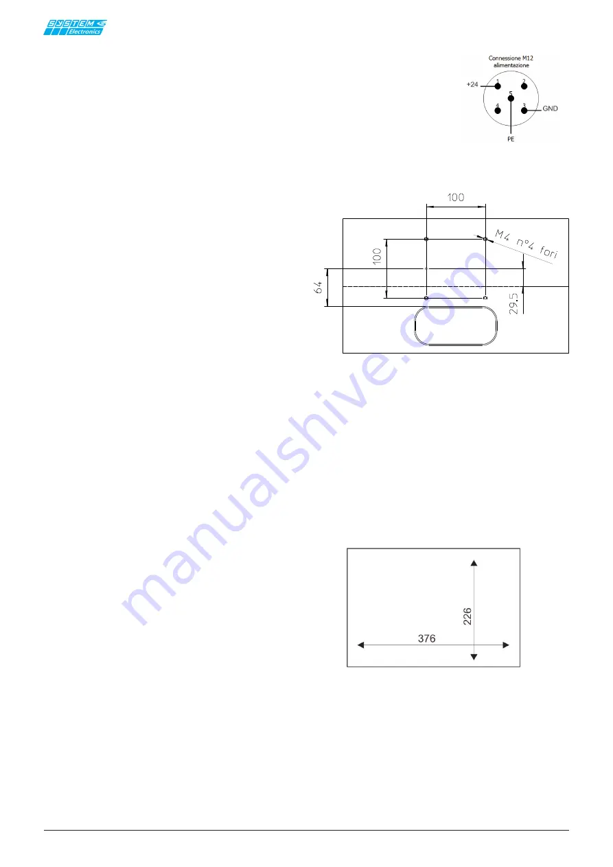
The pinout of the power connector is shown below, as
shown in the manual section:
It is possible to adjust and tighten the VESA 100 joint
of the optional 15.6 '' Copilot column by adjusting the
knobs on the side of the joint.
4.2 Panel mounting
- Drill the panel according to the indicated mea-
surements: 376 x 226
-
Remove the
Copilot 15.6 ''
from the packaging
and place it on a flat surface free of objects, placing a
soft cloth on the table itself to avoid scratching the glass
during the installation phase. Place the 15.6 '' Copilot
with the glass facing the table. Avoid even temporarily
placing the terminal in a vertical position or slightly
resting on the mechanics to avoid damage due to the
unstable position.
- Remove the power connector.
1:
+24V
3:
GND
5:
PE
Figure 4.1.1
Figure 4.1.2 Copilot 15.6 ”fixing positioned on the VESA arm.
Detail of the position of the fixing holes with respect to the axis
and with respect to the lower connectors.
4.2.1 Panel drilling template


