background image

I56-4446-000

DB200-04-00

6

GUÍA

 DE

 MODOS

 DE

 FUNCIONAMIENT

O

 Y

 SOLUCIÓN

 DE

 PROBLEMAS

Pittway Tecnologica S.r.l., Via Caboto 19/3, 34147 TRIESTE, Italy
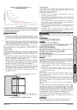
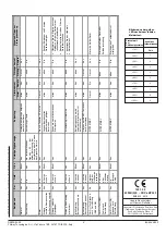
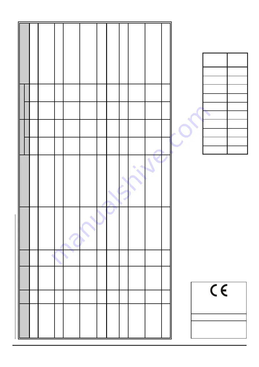
Porcentaje de 

la deriva del 

detector

<10%

<20%

<30%

<40%

<50%

<60%

<70%

<80%

<90%

<100%

1293  20

6500R(S)E  -  DOP-LBP025

EN54-12: 2015

Detector de Humo por Rayo

Honeywell Products and Solutions Sàrl

(Trading as System Sensor Europe)

Zone d’activités La Pièce 16

CH-1180 ROLLE, Switzerland

Número de 

parpadeos

Ninguno

1

2

3

4

5

6

7

8

9

Parpadeos del LED amarillo  

después de que el equipo ha 

superado una prueba local:

Modo

 de 

fu

n

ci

o

n

am

ie

n

to


R

o

jo


Amarillo


Verde


Lect

ura de la

 pa

nt

alla 

di

gi

ta

l (2

 s

eg

me

ntos

Descripci

ón 

o a

cción a


realizar


Con

tactos alar

ma


C

o

n

ta

ct

o

s a

ve

C

o

m

en

ta

ri

o

s y

 p

o

si

b

le

s s

o

lu

ci

o

n

es


Alarma


Remo

ta


A

ve

Remo

ta


Normal


Off


Off


Interm.


Off


Inicialización co

mpleta cor

re

cta 

o rearme 

del det

ector.


Abi

erto 

Off


Cerrad

Off


Alineación 

Off


On


Off


On, núme

ro de 

señal 0-

99, o “- 

-“

si

 se 

re

arma l

autoganan

cia, 

o “Lo” si 

señal dema

siado

 baja. 

Botón de alineaci

ón 

Abierto 

Off


Abierto 

On


Alarma 

On


Off


Off


Off


Humo, filtro de prueba,   

RTS151KEY


Cerrad

o On


Cerrad

o Off


Avería 

- Alcan

za

do 

val

or m

áx. de  

co

m

pe

ns

aci

ón

 p

or


suci

eda

Off


3 parpade

os 

rápidos 

Interm.


Off


Referen

cia de 

co

mpensa

ción 

larga fuera d

e los límites 

Abierto O

ff 

Abierto O


Limpiar el detect

or y 

reflecto


Señal de ave

ría 

– 

Por encim

a d

el 

límite 

Off


2 parpade

os 

rápidos 

Interm.


Off


Aumento de la señal reflejada 

Abierto 

Off


Abierto 

On


Comproba

r que 

en el campo 

visu

al 

entre el dete

ctor 

y refle

ctor n

o ha

ob

je

tos

 r

ef

le

ct

an

te


Luz 

solar  en el d

etecto

r o refle

cto

Avería 

- Bloqueo

 del 

rayo.


Off


4 parpade

os 

rápidos 

Off


Off


Bloqueo del rayo


Abierto 

Off


Abierto 

On


Retirar bloqueo


Unidad de

fe

ctuo

sa


Inic

ializ

ac

ión – 

Alimentación 

cone

ctada


Off


Interm. ha

sta 

finalizar 

Interm.


Off


Aplicar alimentación en equipo 

apagado


Abi

erto 

Off


Cerrad

Off


Inic

ializ

ac

ión-


Fin alineación 

Off


Interm. ha

sta 

finaliza

r  

Interm.


Off


Pulsar botón

 RE

ARME despu

és 

de alineación


Abi

erto 

Off


Cerrad

Off


Prueba local 

con


éxito  

(RE y

 RSE 

ver

si

one

s)  

On

 Parpadeo

según la 

deriva 

produ

cida 

Off

 Off


RTS151KEY


Cerrad

On


Cerrad

Off


Detecto

r en alarma hasta 

que 

se 

rearma


Fallo

 en Prueba 

loc

al  

(RSE Vers

ión) 

Off


'On

' ha

sta 

rearme o 

fin 

de tiempo de 

in

di

ca

ci

ón


Interm.

 Off


RTS151KEY


Abierto 

Off


Abierto 

On


Detecto

r en a

ve

a hasta 

que se 

re

ar

m

a o

 fi

na

liz

a t

ie

m

po

 d

e i

nd

ic

ac

Fallo

 en

 Prueba 

loc

al (

R

E Vers

ión)


Off


Como modo 

averí

Interm.

 Off


RTS151KEY


Abierto 

Off


Abierto 

On


Si falla prueba local, est

ará en 

avería


Leyen

da

: Inte

rm

.: 

In

te

rm

ite

nt

e

; On: 

Ac

tiv

ad

o

; Of

f: 

Desa

cti

vad

o


Summary of Contents for 6500RE

Page 1: ...eiver unit or reflector If the transmitter receiver is mounted on the 6500 MMK BEAMMMK then the 6500 SMK BEAMSMK must be used Note that only a single 20cm x 20cm reflector can be mounted using the MMK...

Page 2: ...RESISTOR SCHOTTKY DIODE A SCHOTTKY DIODE K Figure 4 RTS151KEY Wiring REMOTE ALARM OUTPUT AUX TEST INPUT RESET INPUT WIRING Note All wiring must be installed in accordance with local requirements Warni...

Page 3: ...to connect the optional Schottky diode when used with active end of line monitoring refer to panel manufacturer for details Do not fit the diode unless it is specifically required otherwise the funct...

Page 4: ...e amount of light received from the reflector 1 Install the outer housing of the detector The housing is installed by tightening the four captive screws one in each corner of the housing Note The hous...

Page 5: ...When a test is initiated using the remote test station or local test switch the test filter is moved in the pathway of the light beam If the correct level of signal reduction is received the detector...

Page 6: ...nal Open Off Open On Inspect line of sight between detector and reflector for reflective objects in path Sunlight into detector or reflector Fault Beam Blockage Response Off 4 Quick Blinks Off Off Bea...

Page 7: ...permette il montaggio del rivelatore 6500RE su soffitti o pareti dove l inclinazione massima di 10 non pu essere rispettata Il kit utilizzato per montare il rivelatore o il riflettore Inoltre se il ri...

Page 8: ...SCHOTTKY DIODE K Figura 4 Collegamenti del RTS151KEY NOTA 1 VEDERE LE ISTRUZIONI DEL RTS151KEY PER LE CARATTERISTICHE ELETTRICHE REMOTE ALARM OUTPUT AUX TEST INPUT RESET INPUT COLLEGAMENTI Nota Tutti...

Page 9: ...terminali T5 3 e T5 4 sono usati per connettere un diodo Shottky quando viene usato un fine linea attivo consultare il manuale della centrale per maggiori dettagli Non connettere il diodo se non speci...

Page 10: ...9 In questa fase il sensore regola automaticamente in maniera definitiva il suo guadagno E necessario effettuare questa operazione montando la calotta perch la calotta cambia la quantit di luce rifles...

Page 11: ...orretta attenuazione del segnale viene ricevuta dal rivelatore esso produrr una segnalazione di allarme Se invece l attenuazione elaborata non corretta sensibilit fuori tolleranza il sensore attiver l...

Page 12: ...perto Off Aperto On Verifica assenza oggetti tra rivelatore e pannello verifica assenza oggetti riflettenti a distanza ravvicinata Luce solare sul pannello riflettente Guasto Blocco del raggio rispost...

Page 13: ...kit se monta la unidad con transmisor receptor o el reflector Si se monta el transmisor receptor en el 6500 MMK BEAMMMK se debe utilizar el 6500 SMK BEAMSMK Observe que solo se puede montar un nico re...

Page 14: ...SCHOTTKY A DIODO SCHOTTKY K Figura 4 Conexi n RTS151KEY INSTRUCCIONES DE INSTALACI N DE RTS151KEY PARA LOS VALORES EL CTRICOS DE RTS151KEY ALARMA REMOTA SALIDA AUX PRUEBA ENTRADA REARME ENTRADA V ASE...

Page 15: ...chottky opcional cuando se utiliza con supervisi n activa de final de l nea consulte con el fabricante de la central para m s detalles No instale el diodo a menos que sea estrictamente necesario de lo...

Page 16: ...sa exterior del detector La carcasa se instala apretando los cuatro tornillos uno en cada esquina Nota La carcasa dispone de una junta de estanqueidad sellada que protege la circuiter a del detector d...

Page 17: ...na prueba a trav s de la estaci n de prueba remota o el bot n de prueba local el filtro de prueba se desplaza para bloquear la trayectoria del haz de luz Si se recibe el nivel correcto de reducci n de...

Page 18: ...padeos r pidos Interm Off Referencia de compensaci n larga fuera de los l mites Abierto Off Abierto On Limpiar el detector y reflector Se al de aver a Por encima del l mite Off 2 parpadeos r pidos Int...

Page 19: ...schen Fl che montiert 6500 MMK BEAMMMK Der Befestigungs Satz erm glicht die Decken Wandmontage des Melders oder des Prismen Reflektors Hierbei darf die zul ssige Abweichung von der optischen Achse gr...

Page 20: ...NGSVERSORGUNG ALARM KONTAKT SCHLIESSER BEZUGSPOTENTIAL ALARM ALARM KONTAKT SCHLIESSER BEZUGSPOTENTIAL ALARM ALARM WIDERSTAND ALARM WIDERSTAND SCHOTTKY DIODE A SCHOTTKY DIODE K Abbildung 4 Verdrahtung...

Page 21: ...chalten Hinweise erhalten Sie von dem Hersteller der Zentrale Zur Gew hrleistung der Funktionalit t ist ausschlie lich die spezifizierte Diode zu verwenden Hierbei ist unbedingt auf die richtige Polar...

Page 22: ...haften des reflektierten Lichts hierdurch ver ndern 1 Montieren Sie das Geh useoberteil des Melders Das Geh useoberteil wird mittels der vier Geh useschrauben in den Ecken befestigt Hinweis Um den Mel...

Page 23: ...Verwendung der Fernausl sung zu beachten Der Melder 6500RSE ist mit einem motorbetriebenen geeichten Testfilter ausger stet Der Testfilter ist innerhalb der Melderoptik integriert Der Testfilter wird...

Page 24: ...nalen offen Aus offen Ein berpr fen Sie die Strecke zwischen Melder und Prismen Reflektor auf reflektierende Oberfl chen Sonnenlicht wird durch den Prismen Reflektor reflektiert St rung Strahlenweg is...

Page 25: ...ecteur ne peuvent tre mont s avec un angle inf rieur 10 l un par rapport l autre Le kit permet de monter soit l ensemble metteur r flecteur soit le r flecteur Il est imp ratif d utiliser le 6500 SMK B...

Page 26: ...Y CONSULTER LA NOTICE D INSTALLATION DU RTS151KEY POUR LES CARACTERISTIQUES LECTRIQUES CABLAGE Nota Le c blage doit tre effectu en accord avec la r glementation et normes applicables Avertissement Ava...

Page 27: ...Un shunt et des r sistances suppl mentaires sont fournies pour limiter le courant d alarme en fonction de diff rentes applications Se reporter la notice du constructeur pour conna tre la valeur de la...

Page 28: ...tape avec le bo tier externe en place puisqu il modifie la quantit du signal re u 1 Installer le bo tier externe du d tecteur Il est fix en serrant les 4 vis une chaque coin du bo tier A NOTER Le bo t...

Page 29: ...tol rances le d tecteur g n rera un d rangement Remarque Cette proc dure devrait satisfaire la majorit des exigences de maintenance Effectuer syst matiquement un essai de blocage de faisceau comme in...

Page 30: ...eur D faut coupure faisceau teinte 4 flashs rapides teinte teinte Coupure totale du signal Ouvert Inactive Ouvert Active Enlevez le blocage D tecteur en panne Initialisation mise sous tension teinte F...

Reviews: