background image

I56-4446-000

DB200-04-00

6

OPERA

TION

 MODES

 AND

 TROUBLESHOOTING

 GUIDE

Pittway Tecnologica S.r.l., Via Caboto 19/3, 34147 TRIESTE, Italy

Percent the 

detector has 

drifted

<10%

<20%

<30%

<40%

<50%

<60%

<70%

<80%

<90%

<100%

Number 

of blinks  

output

None

1

2

3

4

5

6

7

8

9

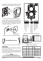
Blinks Output by Yellow 

LED once the Device has 

Passed a Local Test 

Mo

d

es 

R

ed


Yellow 

G

reen


Dua

l Digita

l Dis

p

la

Re

adout


In

it

ia

ti

n

g

 M

ea

n

A

larm C

o

n

tac

ts


Fa

ult

 Cont

ac

ts 

Comme

nt

s a

nd 

Tr

ouble

shoot

ing Tips


Ala

rm


R

em

o

te


Fa

ult


R

em

o

te


Normal


Off 

Off 

Blink

 Off 

S

ucc

es

sfu

l c

omp

le

tion of 

init

ial

is

ati

on or de

tect

or re

se

O

pe

O

ff 

C

lo

se


O

ff  

Alignm

ent


Off On 

Off 

On, 

re

la

tiv

e amo

un

t of 

si

gn

al

 0-

99

, o

r “

- -“

 if


aut

o gai

re

se

ttin

g, or 

“L

o”

 if

 si

gn

al

 too

 low 

A

lignm

ent

 S

w

itch


O

pen


O

ff 

O

pen


O


Alarm


On Off 

Off 

Off 

S

m

oke,

 T

est

 F

ilt

er

, R

T

S

151 

KEY


C

lo

se


On


C

lo

se


O

ff  

Fault 

- Dri

ft Com

Li

mi

t R

eac

he

Off 

3 Q

ui

ck


Blink

Blink

 Off 

Lo

ng term

 dr

ift re

fe

re

nc

e out


of

 ra

ng

O

pen


O

ff 

O

pen

 O


C

lea

n d

et

ect

or 

an

d r

efl

ect

or


F

ault S

ign

al 

– O

ver 

R

an

ge


Off 

2 Q

ui

ck


Blink

B

link


O

ff 

Inc

re

as

e o

f r

efl

ec

ted 

si

gn

al


O

pen


O

ff 

O

pen


O


Ins

pe

ct lin

e of sig

ht betw

ee

det

ec

tor

 a

nd 

re

fle

cto

r f

or 

refl

ec

tiv

e obj

ec

ts i

pa

th


S

unli

ght

 in

to 

de

te

cto

r o

refl

ec

to

F

ault -

 B

eam 

B

lock

ag

e R

esp

on

se


Off 

4 Q

ui

ck


Blink

Off 

Off 

Beam Blo

ck

ag

O

pen


O

ff 

O

pen

 O


Re

mo

ve

 Bl

oc

ka

ge 


Fa

ul

ty

 Un

it 

Init

ial

is

ati

on – 

Po

wer 

On


Off 

Blink un

til 

comp

let

Blink

 Off 

A

ppl

y P

ow

er

 fr

om

 di

sch

ar

ge

st

at

O

pe

O

ff 

C

lo

se


O

ff  

Init

ial

is

ati

on-


A

lignm

ent

 E

xit


Off 

Blink un

til 

comp

let

Blink

 Off 

De

pr

es

si

ng

 RESET s

witch


af

ter

 a

lig

nm

en

O

pe

O

ff 

C

lo

se


O

ff  

Lo

cal

 T

est


P

ass 

re

su

lt  


(R

E & RSE Ve

rs

ion

s)


On


Blink

s o

ut 

amou

nt of 

dr

ift

 us

ed 

Off Off 

RTS1

51

KEY


Clo

se 

On


Clo

se 

Off 

D

et

ec

to

r r

em

ai

ns

 in

 a

la

rm

 u

nt

il 

re

set


Lo

cal

 Te

st


Fail r

es

ult


(RSE Ve

rs

ion

Off 

On u

ntil


res

et of 

timeo

ut


Blink

 Off 

RTS151KEY 

O

pen


O

ff 

O

pen

 O

Dete

cto

r r

emai

ns

 in

 faul

t u

nti

res

et or

 time

ou

Lo

cal

 Te

st


Fail Re

sul

t   


(R

E Ve

rs

io

n) 

Off 

As fa

ult 

mode


Blink

 Off 

RTS151KEY 

O

pen


O

ff 

O

pen

 O

If l

oc

al

 te

st

 fa

ils

 w

ill

 a

lre

ad

be

 in


fau

lt 


1293  20

6500R(S)E  -  DOP-LBP025

EN54-12: 2015

Optical Beam Smoke Detector

Intended for use in fire detection and fire 

alarm systems in and around buildings

Honeywell Products and Solutions Sàrl

(Trading as System Sensor Europe)

Zone d’activités La Pièce 16

CH-1180 ROLLE, Switzerland

Summary of Contents for 6500RE

Page 1: ...eiver unit or reflector If the transmitter receiver is mounted on the 6500 MMK BEAMMMK then the 6500 SMK BEAMSMK must be used Note that only a single 20cm x 20cm reflector can be mounted using the MMK...

Page 2: ...RESISTOR SCHOTTKY DIODE A SCHOTTKY DIODE K Figure 4 RTS151KEY Wiring REMOTE ALARM OUTPUT AUX TEST INPUT RESET INPUT WIRING Note All wiring must be installed in accordance with local requirements Warni...

Page 3: ...to connect the optional Schottky diode when used with active end of line monitoring refer to panel manufacturer for details Do not fit the diode unless it is specifically required otherwise the funct...

Page 4: ...e amount of light received from the reflector 1 Install the outer housing of the detector The housing is installed by tightening the four captive screws one in each corner of the housing Note The hous...

Page 5: ...When a test is initiated using the remote test station or local test switch the test filter is moved in the pathway of the light beam If the correct level of signal reduction is received the detector...

Page 6: ...nal Open Off Open On Inspect line of sight between detector and reflector for reflective objects in path Sunlight into detector or reflector Fault Beam Blockage Response Off 4 Quick Blinks Off Off Bea...

Page 7: ...permette il montaggio del rivelatore 6500RE su soffitti o pareti dove l inclinazione massima di 10 non pu essere rispettata Il kit utilizzato per montare il rivelatore o il riflettore Inoltre se il ri...

Page 8: ...SCHOTTKY DIODE K Figura 4 Collegamenti del RTS151KEY NOTA 1 VEDERE LE ISTRUZIONI DEL RTS151KEY PER LE CARATTERISTICHE ELETTRICHE REMOTE ALARM OUTPUT AUX TEST INPUT RESET INPUT COLLEGAMENTI Nota Tutti...

Page 9: ...terminali T5 3 e T5 4 sono usati per connettere un diodo Shottky quando viene usato un fine linea attivo consultare il manuale della centrale per maggiori dettagli Non connettere il diodo se non speci...

Page 10: ...9 In questa fase il sensore regola automaticamente in maniera definitiva il suo guadagno E necessario effettuare questa operazione montando la calotta perch la calotta cambia la quantit di luce rifles...

Page 11: ...orretta attenuazione del segnale viene ricevuta dal rivelatore esso produrr una segnalazione di allarme Se invece l attenuazione elaborata non corretta sensibilit fuori tolleranza il sensore attiver l...

Page 12: ...perto Off Aperto On Verifica assenza oggetti tra rivelatore e pannello verifica assenza oggetti riflettenti a distanza ravvicinata Luce solare sul pannello riflettente Guasto Blocco del raggio rispost...

Page 13: ...kit se monta la unidad con transmisor receptor o el reflector Si se monta el transmisor receptor en el 6500 MMK BEAMMMK se debe utilizar el 6500 SMK BEAMSMK Observe que solo se puede montar un nico re...

Page 14: ...SCHOTTKY A DIODO SCHOTTKY K Figura 4 Conexi n RTS151KEY INSTRUCCIONES DE INSTALACI N DE RTS151KEY PARA LOS VALORES EL CTRICOS DE RTS151KEY ALARMA REMOTA SALIDA AUX PRUEBA ENTRADA REARME ENTRADA V ASE...

Page 15: ...chottky opcional cuando se utiliza con supervisi n activa de final de l nea consulte con el fabricante de la central para m s detalles No instale el diodo a menos que sea estrictamente necesario de lo...

Page 16: ...sa exterior del detector La carcasa se instala apretando los cuatro tornillos uno en cada esquina Nota La carcasa dispone de una junta de estanqueidad sellada que protege la circuiter a del detector d...

Page 17: ...na prueba a trav s de la estaci n de prueba remota o el bot n de prueba local el filtro de prueba se desplaza para bloquear la trayectoria del haz de luz Si se recibe el nivel correcto de reducci n de...

Page 18: ...padeos r pidos Interm Off Referencia de compensaci n larga fuera de los l mites Abierto Off Abierto On Limpiar el detector y reflector Se al de aver a Por encima del l mite Off 2 parpadeos r pidos Int...

Page 19: ...schen Fl che montiert 6500 MMK BEAMMMK Der Befestigungs Satz erm glicht die Decken Wandmontage des Melders oder des Prismen Reflektors Hierbei darf die zul ssige Abweichung von der optischen Achse gr...

Page 20: ...NGSVERSORGUNG ALARM KONTAKT SCHLIESSER BEZUGSPOTENTIAL ALARM ALARM KONTAKT SCHLIESSER BEZUGSPOTENTIAL ALARM ALARM WIDERSTAND ALARM WIDERSTAND SCHOTTKY DIODE A SCHOTTKY DIODE K Abbildung 4 Verdrahtung...

Page 21: ...chalten Hinweise erhalten Sie von dem Hersteller der Zentrale Zur Gew hrleistung der Funktionalit t ist ausschlie lich die spezifizierte Diode zu verwenden Hierbei ist unbedingt auf die richtige Polar...

Page 22: ...haften des reflektierten Lichts hierdurch ver ndern 1 Montieren Sie das Geh useoberteil des Melders Das Geh useoberteil wird mittels der vier Geh useschrauben in den Ecken befestigt Hinweis Um den Mel...

Page 23: ...Verwendung der Fernausl sung zu beachten Der Melder 6500RSE ist mit einem motorbetriebenen geeichten Testfilter ausger stet Der Testfilter ist innerhalb der Melderoptik integriert Der Testfilter wird...

Page 24: ...nalen offen Aus offen Ein berpr fen Sie die Strecke zwischen Melder und Prismen Reflektor auf reflektierende Oberfl chen Sonnenlicht wird durch den Prismen Reflektor reflektiert St rung Strahlenweg is...

Page 25: ...ecteur ne peuvent tre mont s avec un angle inf rieur 10 l un par rapport l autre Le kit permet de monter soit l ensemble metteur r flecteur soit le r flecteur Il est imp ratif d utiliser le 6500 SMK B...

Page 26: ...Y CONSULTER LA NOTICE D INSTALLATION DU RTS151KEY POUR LES CARACTERISTIQUES LECTRIQUES CABLAGE Nota Le c blage doit tre effectu en accord avec la r glementation et normes applicables Avertissement Ava...

Page 27: ...Un shunt et des r sistances suppl mentaires sont fournies pour limiter le courant d alarme en fonction de diff rentes applications Se reporter la notice du constructeur pour conna tre la valeur de la...

Page 28: ...tape avec le bo tier externe en place puisqu il modifie la quantit du signal re u 1 Installer le bo tier externe du d tecteur Il est fix en serrant les 4 vis une chaque coin du bo tier A NOTER Le bo t...

Page 29: ...tol rances le d tecteur g n rera un d rangement Remarque Cette proc dure devrait satisfaire la majorit des exigences de maintenance Effectuer syst matiquement un essai de blocage de faisceau comme in...

Page 30: ...eur D faut coupure faisceau teinte 4 flashs rapides teinte teinte Coupure totale du signal Ouvert Inactive Ouvert Active Enlevez le blocage D tecteur en panne Initialisation mise sous tension teinte F...

Reviews: