


I56-4157-002
Pittway Tecnologica S.r.l. Via Caboto 19/3, 34147 TRIESTE, Italy
DESCRIPTION
The M200WC-RF is an interface that connects to a PC through
a USB port and allows communication with System Sensor 200
Series Commercial RF devices. The M200WC-RF is powered
directly by the USB port.
This radio device complies with the requirements of 2014/53/EU
for conformance with the RED directive.
SPECIFICATIONS
Supply Voltage:
4.3 – 5.5V Direct Current (DC)
Supply Current:
33mA typical @ 5VDC
USB standard:
USB 2.0 (full speed)
USB connector:
Type A
Radio Frequency: 865-870 MHz;
RF Output Power: 13 dBm (@ 5VDC)
Range:
130m (typ. in free air)
Relative Humidity: 10% to 93% (non-condensing)
INSTALLATION
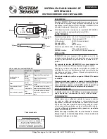
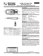
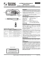
The M200WC-RF has an adjustable USB connector in order to
maximize the RF coupling with radio communicating devices, and
to change its profile when connected to a portable PC.
Do not connect the M200WC-RF interface until the correct
drivers have been installed on the target PC.
Download the latest version of the AgileIQ
®
radio interface software
(with the correct interface drivers) from a trusted source - see the
Radio Programming and Commissioning Manual
for the installation
procedure.
Only plug the RF interface into a spare USB port on the PC
when requested.
Note that when the interface is attached, Windows may take a
number of seconds to recognize the new hardware correctly;
always wait a short period for the LED to change from yellow
to green before proceeding with any other operation.
LED INDICATORS
The interface is equipped with an RGB LED, giving an indication of
power and communication (both RF and USB) status (see table).
PROGRAMMING
Used in conjunction with the PC application software M200SCT-RF,
the RF interface is used to program and communicate with System
Sensor 200 Series RF fire detection devices. For information on
setting-up, commissioning and monitoring an RF mesh network,
see the
Radio Programming and Commissioning Manual
- ref.
D200-306-00.)
NOTE:
Do not run more than one interface at a time to
commission devices or carry out a site survey in an area.
M200WC-RF
RADIO SYSTEM USB INTERFACE
INSTALLATION AND USER INSTRUCTIONS
E N G L I S H
96 mm
31 mm
76 mm
26 mm
USB Connector
- Type A
(Hidden)
LED
13 mm
8.4 mm
0°C
50°C
M200WC-RF interface status LED
Status
LED State Meaning
Power-on initialisation
Green pulse Device OK and connected
Amber ON Device OK but not recognized
Fault
Amber blink Device has an internal trouble
Serial (USB)
communication
Green blink Interface is receiving data from
the PC application
RF communication
Blue blink
Interface is receiving data from
an RF device
Patents Pending
I 56- 4157- 002
EU Declaration of Conformity
Hereby,
Life Safety Distribution GmbH declares
that the radio equipment type
M200WC-RF
is in
compliance
with directive 2014/53/EU
The full text of the EU DoC can be requested from:
HSFREDDoC@honeywell.com


