Page 4
A05-239-03
Ordering Information
Models – ADA Compliant, UL 1971 Listed
Operating
Strobe Current
Product
Electromech. Tone
Voltage
(Average mA)
Candela
Signaling Strobes
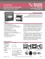
SS2415ADAS
Signaling Strobe with Sync•Circuit
24 VDC
106
15
SS241575ADAS**
Signaling Strobe with Sync•Circuit
24 VDC
195
15/75
Multi-Alert Sounder with Signaling Strobe
MASS2415ADAS
Sounder with Signaling Strobe with Sync•Circuit
MAEH2415ADAS
24 VDC
*
15
MASS241575ADAS**
Sounder with Signaling Strobe with Sync•Circuit
MAEH241575ADAS
24 VDC
*
15/75
*Total current = strobe c sounder current
**UL 1971 listed to 15 cd. Recommended for areas 20
′
×
20
′
or smaller.
How to Order
SS2415ADAS
Synchronizable Strobe
24 Volt
SS = Signal Strobe
MASS = Multi-Alert Sounder/Strobe
MAEH = Multi-Alert Sounder/Strobe
with Electromechanical Tone
15 = 15 cd, UL 1971 Strobe
1575 = 15 cd UL 1971
Electrical Ratings – Strobe Only
Average Operating Current
Operating Current from
Supply
from Regulated
Peak Operating
Full Wave Rectified,
Model
Voltage Range
Supply (mA)
Current (mA)
Unfiltered Supply (mArms)*
SS2415ADAS
20–30VDC
106
200
125
SS241575ADAS
20–30VDC
195
350
180
* For additional information, see installation manual D900-06-00; for EH models, see installation manual D900-12-00.
Engineering Specifications
Strobe shall be a System Sensor Model ______ listed to
Standard UL 1971 for the Hearing Impaired
and shall be
approved for Fire Protective Service. Strobe shall be wired
as a Primary Signaling Notification appliance. Strobe shall
also comply with the Americans with Disabilities Act
requirements for visible signaling appliances. Strobe shall
operate at 24VDC from a regulated DC supply or full-wave
rectified, unfiltered supply. The signaling strobe shall be
powered from a non-coded power supply when powered
with the horn or powered independently. Visual signaling
devices are to be installed in all non-sleeping/corridor and
sleeping areas (110 cd only) per plans and specifications.
The strobe light shall consist of a xenon flash tube and
associated lens/reflector system. Each strobe shall be
designed for one flash per second over all operating
conditions. All strobes shall be capable of mounting to a
standard 4
″
×
4
″
×
1
1
/
2
″
backbox, in either a surface mount
or semiflush mount with separate mounting plate. Strobe
shall flash synchronously with other SS24ADAS and
MASS24ADAS Series devices in the same zone for a
minimum of 15 minutes.
Note: SS24ADAS,
MASS24ADAS and MAEH24ADAS Series devices
operating in the same zone will not be synchronized if
energized at different times (i.e., if more than one
controller is controlling the same zone).
System Sensor Worldwide Distribution
In Canada:
System Sensor Canada
6581 Kitimat Road, Unit #7
Mississauga, Ontario
Canada L5N 3T5
Telephone: 905-812-0767
Fax: 905-812-0771
In the United Kingdom:
System Sensor Europe, Ltd.
Horsham Gates III, North St.
Horsham, West Sussex
RH13 5PJ, United Kingdom
Telephone: 44-1403-276500
Fax: 44-1403-276501
In India:
System Sensor India
A-204 Maheshwari Nagar
Orkay Mills Lane
Andheri East, Mumbai 400093
Telefax: 91-022-8202564
In the Far East:
System Sensor
Pittway Far East, Ltd.
Suite 706, New T&T Centre
7 Canton Road
Tsimshatsui, Kowloon, Hong Kong
Telephone: 852-2730-9090
Fax: 852-2736-6580


