background image

FDR-3G

Circular Fire Damper

Handbook

Summary of Contents for 163262

Page 1: ...FDR 3G Circular Fire Damper Handbook ...

Page 2: ...2 67 FDR 3G Table of Contents Overview 3 Technical Parameters 7 Diagrams 10 Dimensions Weights 12 Ordering Code 14 Installation 16 Electrical Parameters 42 Operation Manual 65 ...

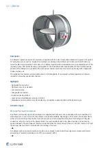
Page 3: ...hangeable mechanism Inspection opening built in Great variety of installations rated up to EI120S Modulated actuator suitable for system balancing possibility to open the blade at the desired angle Activation Types Manually Operated Fire Dampers By default all manually operated fire dampers are supplied with manual control optionally with micro switches and electromagnets In case of fire the fire ...

Page 4: ...g return actuator AC DC 24 V with electro thermal fuse 72 C and auxiliary switches B24T W or G24T W Fire damper with an activation mechanism with a Belimo or Gruner spring return actuator AC DC 24 V with an electro thermal fuse 72 C and auxiliary switches with provided cable connectors for the supply and communication unit communication unit not part of the mechanism B24T SR or G24T SR Fire damper...

Page 5: ...d an intumescent seal that expands in a fire situation Material Composition The product contains galvanized sheet metal calcium silicate board fireproof carbon fiberglass polyurethane foam and ethylene propylene rubber These are processed in accordance with local regulations The product contains no hazardous substances except for the solder in the thermofuse which contains a milligram of lead List...

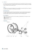
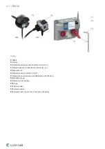
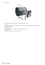
Page 6: ...tuator operated activation mechanism B G P5 Inspection lid P6 Thermoelectric fuse BAT72 TA 72 P7 Supply and communication unit BKN230 24 FS UFC24 2 P8 Bendable hanger P9 Release and test button P10 Crank P11 Open position P12 Closed position P13 Hexagon bent wrench No 10 not part of delivery ...

Page 7: ...of the thermal fuse Actuator operated 72 C as standard 95 C or 120 C on request with Belimo actuator by means of the spring after current interruption in the electro thermal fuse Operational temperature Minimum 0 C Maximum 60 C for 74 C and 72 C thermal fuse Maximum 85 C for 95 C and 100 C thermal fuse Maximum 105 C for 120 C thermal fuse Environment suitability Protected against weather disruptio...

Page 8: ... T BF24 T BF24 SR T BFN230 T BFN24 T BFN24 T BFL230 T BFL24 T BFL24 SR T also with connection possibilities with acronyms ST W Gruner 360TA 230 12 S2 360CTA 024 12 S2 360TA 024 12 S2 340TA 230D 03 S2 340TA 024D 03 S2 340CTA 024D 03 S2 340TA 230 05 S2 340TA 024 05 S2 340CTA 024 05 S2 also with connection possibilities with acronyms ST W Transport and Storage Dry indoor conditions with a temperature...

Page 9: ...Response delay response time Pass closure time Operational reliability Pass motorized cycle 10 200 cycles manual cycle 50 cycles modulated 20 200 cycles Fire resistance Resistivity depending on installation method and situation integrity E maintenance of the cross section under E mechanical stability under E cross section under E insulation I smoke leakage S Durability of response delay Pass sensi...

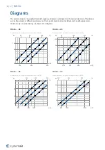
Page 10: ...ze 100 Size 125 Size 140 25 30 35 40 45 50 25 30 35 40 45 50 55 25 30 35 40 45 50 FDR 3G H0 Pressure drop A weighted sound power level in dB A 200 300 500 m h 50 100 200 l s 10 50 100 Pa Size 150 Size 160 Size 180 25 30 35 40 45 50 25 30 35 40 45 50 55 25 30 35 40 45 50 FDR 3G H0 Pressure drop A weighted sound power level in dB A 500 800 1000 m h 200 300 500 l s 5 10 20 Pa Size 200 Size 225 Size 2...

Page 11: ...35 40 45 50 FDR 3G H0 Pressure drop A weighted sound power level in dB A 3000 5000 8000 m h 800 1000 2000 l s 1 5 10 Pa Size 560 Size 630 Size 710 25 30 35 40 45 50 25 30 35 40 45 50 25 30 35 40 45 50 FDR 3G H0 Pressure drop A weighted sound power level in dB A 5000 10000 20000 m h 2000 3000 5000 l s 0 5 1 5 Pa Size 800 Size 900 Size 1000 25 30 35 40 45 50 25 30 35 40 45 50 25 30 35 40 45 50 ...

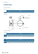
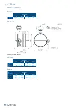
Page 12: ... Overhangs DN mm 100 125 140 150 160 180 200 225 250 280 315 355 400 450 500 560 630 R1 mm 300 287 5 280 275 270 260 250 237 5 225 210 192 5 172 5 150 125 100 70 35 R2 mm 67 54 5 47 42 37 27 17 4 5 8 23 40 5 60 5 83 108 133 163 198 Weights m kg 5 DN mm 100 125 140 150 160 180 200 225 250 280 315 355 400 450 500 560 630 H0 H 3 3 3 4 3 6 3 7 3 8 4 2 4 4 4 8 5 3 5 8 6 4 7 3 8 3 11 1 12 3 14 6 17 0 B ...

Page 13: ...N mm 710 800 900 1000 AV m2 0 357 0 459 0 587 0 731 Dimensions Note 3 Inclusive bearing Overhangs DN mm 710 800 900 1000 R1 mm 3 48 98 148 R2 mm 191 236 286 336 Weights m kg 5 DN mm 710 800 900 1000 H0 H 33 5 39 4 46 5 54 2 B G 35 6 41 5 48 6 56 3 ...

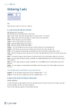
Page 14: ...y and communication unit FSC UFC24 2 Modbus BACnet 24V AC DC Gruner spring return Actuator BST1 SLC powered supply and communication unit BC24 G2 THC 24V AC DC Belimo spring return actuator BST2 230 V AC supply and communication unit BKN230 24 MOD Modbus BACnet 24V AC DC Belimo spring return actuator BST3 230 V AC supply and communication unit BKN230 24 C MP SBS MP 24V AC DC Belimo spring return a...

Page 15: ...0 No inspection opening Inspection possible through removable mechanism or additional inspection opening must be added to the conecting duct ø 160 DN ø225 Standardardly in position L Additional inspection opening cannot be added ø 250 DN ø1000 Standardardly in position B On demand in position L T ...

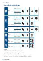
Page 16: ...I 60 ve i o S a b 360 EI 90 ve i o S 5 1 On Out FDR 3G DN100 DN400 EI 60 ve i o S a b EI 90 ve i o S 5 2 On Out FDR 3G DN100 DN500 EI 60 ve i o S a b Legend 1 Wet Wet Installation Using Plaster Mortar Concrete Filling 2 Dry Dry Installation using cover boards and mineral wool filing 3 Soft Soft Installation using mineral wool filing 3H Hilti Filling made only from Hilti foam 5 1 On Out ON OUT of t...

Page 17: ...ensator on either end of the damper The damper driving mechanism can be placed on either side of the wall however it needs to be placed so as to ensure easy access during inspection According to the standard EN 1366 2 the distance between the fire damper bodies must be at least 200 mm This condition does not apply for tested distances Therefore installations Wet and Soft are approved for smaller d...

Page 18: ... inside of the damper 6 If needed uncover and clean the damper after installation 7 Check the damper s functionality Installation Standard Distances According to the standard EN 1366 2 the minimum distance from the wall or ceiling to the damper body is 75 mm For multiple crossings through a fire resistive wall the minimum distance between two damper bodies is 200 mm This applies to distances betwe...

Page 19: ...19 67 FDR 3G ...

Page 20: ...20 67 FDR 3G ...

Page 21: ...s 4d Mineral wool thickness cubic density see picture 5 Flexible wood beam wall 5a Vertical spruce wooden beam 60 100 mm 5b Horizontal spruce wooden beam 80 100 mm 6 Alternative thinner wall classified in accordance with EN 13501 2 2007 A1 2009 for fire resistance required for product application 7 Area of 200 mm from opening around the damper must have the same composition and be created the same...

Page 22: ...r damper use CBS FD cover boards with screws F1 through pre drilled holes 5 All the gaps between the cover boards between cover boards and the wall and between cover boards and the fire damper need to be filled with fire resistive coating F4 6 If needed uncover and clean the damper after installation 7 Check the damper s functionality Installation Standard Distances For Dry installation the minimu...

Page 23: ...23 67 FDR 3G ...

Page 24: ...24 67 FDR 3G ...

Page 25: ...d fireproof plate type F EN 520 4b Vertical CW profiles 4c Horizontal CW profiles 4d Mineral wool thickness cubic density see picture 5 Flexible wood beam wall 5a Vertical spruce wooden beam 60 100 mm 5b Horizontal spruce wooden beam 80 100 mm 6 Alternative thinner wall classified in accordance with EN 13501 2 2007 A1 2009 for fire resistance required for product application 7 Area of 200 mm from ...

Page 26: ...bendable hangers and suitable screws F1 apply the same fire resistive coating F6 at least 2 mm thick and 100 mm wide on the exposed filling and wall edges evenly from both sides Do not apply this layer in the place where the mechanism is located inspection openings and manufacturer labels 5 If needed uncover and clean the damper after installation 6 Check the damper s functionality Installation St...

Page 27: ...27 67 FDR 3G ...

Page 28: ...28 67 FDR 3G ...

Page 29: ...board fireproof plate type F EN 520 4b Vertical CW profiles 4c Horizontal CW profiles 4d Mineral wool thickness cubic density see picture 5 Flexible wood beam wall 5a Vertical spruce wooden beam 60 100 mm 5b Horizontal spruce wooden beam 80 100 mm 6 Alternative thinner wall classified in accordance with EN 13501 2 2007 A1 2009 for fire resistance required for product application 7 Area of 200 mm f...

Page 30: ...you can cut the excess foam that stands out from the wall 5 If needed uncover and clean the damper after installation 6 Check the damper s functionality Installation Standard Distances According to the standard EN 1366 2 the minimum distance from the wall or ceiling to the damper body is 75 mm For multiple crossings through a fire resistive wall the minimum distance between two damper bodies is 20...

Page 31: ...31 67 FDR 3G ...

Page 32: ...EN 520 4b Vertical CW profiles 4c Horizontal CW profiles 4d Mineral wool thickness cubic density see picture 5 Flexible wood beam wall 5a Vertical spruce wooden beam 60 100 mm 5b Horizontal spruce wooden beam 80 100 mm 6 Alternative thinner wall classified in accordance with EN 13501 2 2007 A1 2009 for fire resistance required for product application 7 Area of 200 mm from opening around the damper...

Page 33: ...33 67 FDR 3G Notes ve Vertical wall 1 Smaller distances maximum resistivity EI90 ve i o S ...

Page 34: ...he damper and duct parts between the damper and the wall Glue the insulation onto the wall using suitable fire resistive coating BSF ISOVER Bind the circular damper part and duct insulation with a binding wire 9 for both layers of insulation in the usual way that is applied when insulating circular ducts 6 Cover the insulation face and perimeter up to 150 mm from the insulation edge using galvaniz...

Page 35: ...35 67 FDR 3G ...

Page 36: ...36 67 FDR 3G ...

Page 37: ... Alu1 ISOVER min 66 kg m3 inner layer outer layer 9 Steel binding wire thickness 1 6 mm 10 Screw 3 9 max 13 e g DIN7504 11 Steel threaded rod M12 1 12 Ceramic tape A KERA width 40 mm thickness 2 mm 13 Sheet metal ringlet for damper suspension MP MX HILTI when using 1 M12 rod 14 Sheet metal ringlet for damper suspension UVH30 Lindab when using 2 M10 rod 15 Steel threaded rod M10 2 16 Nut M10 4 Note...

Page 38: ...Lindab 14 with nuts 16 5 Insulate the damper and duct parts between the damper and the wall Entwine the circular damper and duct with one layer of insulation 17 Glue the insulation onto the wall using a suitable fire resistive coating F10 Secure the insulation 17 with a binding wire ř 1 6 mm in the standard way that is applied when insulating circular ducts or by using wire clamps 26 to sew togeth...

Page 39: ...39 67 FDR 3G ...

Page 40: ...40 67 FDR 3G ...

Page 41: ...sion MP MX HILTI when using 1 M12 rod 14 Sheet metal ringlet for damper suspension UVH30 Lindab when using 2 M10 rod 15 Steel threaded rod M10 2 16 Nut M10 4 17 Mineral wool ULTIMATE Protect Slab 4 0 Alu1 ISOVER min 66 kg m3 25 Aluminium tape around the front side and on places uncovered with alufoil 26 Wire clamp for U ProtectWiredMat fixation Notes ve Vertical wall 5 Rules for hanger placements ...

Page 42: ... T ST BST0 11 VA BF24 T ST BKN230 24 B24T SR KR 9 5 VA BF24 T SR T PC A DN mm 100 125 140 150 160 180 200 225 250 280 315 355 400 450 500 560 630 710 800 900 1000 G230T KR 9 5 VA 340TA 230 05 G24T KR 9 VA 340TA 024 05 G24T W KR 9 VA 340TA 024 05 ST01 GST0 KR 11 VA 340TA 024 05 ST01 fs UFC24 2 G24T SR KR 7 5 VA 340CTA 024 05 G230T KR 11 5 VA 360TA 230 12 G24T KR 7 VA 360TA 024 12 G24T W KR 7 VA 360...

Page 43: ...electrical system Microswitch Power Supply 125 250V AC or 12 24V DCElectric Parameters 3A NOTES Supply via safety isolation transformer Power consumption must be observed Legend 1 Grey cable colour 2 Orange cable colour 3 Pink cable colour 4 White cable colour 5 Red cable colour 6 Brown cable colour Do not use for type of activation H2 X 7 Blue cable colour Do not use for type of activation H2 ...

Page 44: ...4V DC Electric Parameters 3A Impulse Electromagnet Power Supply AC 50 60 Hz DC 24 V Electric Parameters 50 VA load factor 10 maximum 30 seconds in operation NOTES 50 VA Nominal activation power maximum permissible magnet load 300 VA Supply via safety isolation transformer Power consumption must be observed Legend 1 Grey cable colour 2 Orange cable colour 3 Pink cable colour 4 White cable colour 5 ...

Page 45: ...r Supply 230V AC 50 60 Hz Electric Parameters 50 VA load factor 10 maximum 30 seconds in operation NOTES 50 VA Nominal activation power maximum permissible magnet load 300 VA Caution Main power supply voltage A device that disconnects the pole conductors minimum contact gap 3 mm is required for isolation from the power supply Power consumption must be observed Legend 1 Grey cable colour 2 Orange c...

Page 46: ...50 60 Hz NOTES Caution Main power supply voltage A device that disconnects the pole conductors minimum contact gap 3 mm is required for isolation from the power supply Parallel connection of several actuators possible Power consumption must be observed Legend 1 Blue cable colour 2 Brown cable colour S1 Violet cable colour S2 Red cable colour S3 White cable colour S4 Orange cable colour S5 Pink cab...

Page 47: ...50 60 Hz NOTES Caution Main power supply voltage A device that disconnects the pole conductors minimum contact gap 3 mm is required for isolation from the power supply Parallel connection of several actuators possible Power consumption must be observed Legend 1 Blue cable colour 2 Brown cable colour S1 Violet cable colour S2 Red cable colour S3 White cable colour S4 Orange cable colour S5 Pink cab...

Page 48: ...NOTES Supply via safety isolation transformer Parallel connection of several actuators possible Power consumption must be observed Legend 1 Blue cable colour black for BF24 T 2 Red cable colour white for BF24 T S1 Violet cable colour white for BF24 T S2 Red cable colour white for BF24 T S3 White cable colour white for BF24 T S4 Orange cable colour white for BF24 T S5 Pink cable colour white for BF...

Page 49: ...on the electrical system Actuator power supply AC 50 60 Hz DC 24 V NOTES Supply via safety isolation transformer Parallel connection of several actuators possible Power consumption must be observed Legend 1 Black cable colour 2 Red cable colour S1 Violet cable colour S2 Red cable colour S3 White cable colour S4 Orange cable colour S5 Pink cable colour S6 Grey cable colour Tf Thermal fuse ...

Page 50: ...z DC 24 V NOTES Supply via safety isolation transformer Parallel connection of several actuators possible Power consumption must be observed Legend 1 Blue cable colour black for BF24 T in connector 1 2 Brown cable colour white for BF24 T in connector 1 S1 Violet cable colour white for BF24 T in connector 2 S2 Red cable colour white for BF24 T in connector 2 S3 White cable colour white for BF24 T i...

Page 51: ...ly via safety isolation transformer Parallel connection of several actuators possible Power consumption must be observed Legend 1 Black cable colour black for BF24 T in connector 1 2 Red cable colour white for BF24 T in connector 1 S1 Violet cable colour white for BF24 T in connector 2 S2 Red cable colour white for BF24 T in connector 2 S3 White cable colour white for BF24 T in connector 2 S4 Oran...

Page 52: ...work on the electrical system Actuator power supply AC 50 60 Hz DC 24 V NOTES Supply via safety isolation transformer Power consumption must be observed Legend 1 Blue cable colour 2 Brown cable colour 3 White cable colour 5 Orange cable colour S1 Violet cable colour S2 Red cable colour S3 White cable colour S4 Orange cable colour S5 Pink cable colour S6 Grey cable colour Tf Thermal fuse ...

Page 53: ... work on the electrical system Actuator power supply AC 50 60 Hz DC 24 V NOTES Supply via safety isolation transformer Power consumption must be observed Legend 1 Blue cable colour 2 Brown cable colour 3 Black cable colour 4 Grey cable colour S1 Violet cable colour S2 Red cable colour S3 White cable colour S4 Orange cable colour S5 Pink cable colour S6 Grey cable colour Tf Thermal fuse ...

Page 54: ...d Actuator power supply AC 50 60 Hz DC 24 V NOTES Connection scheme for standardly fitted BKN230 24 Power consumption must be observed LEDs status indication of actuator BST0 LED colour LED state Status Yellow ON Damper open Yellow Blinks Damper is opening Green ON Damper closed Green Blinks Damper is closing Yellow or green Blinks at double frequency Error Yellow and green OFF Power failure 1 2 3...

Page 55: ...r factory fitted Can be removed if necessary to be replaced by a thermoelectric trip the safety function will be triggered if terminals 1 and 2 are not linked 3 4 Use Jumper only for commissioning purposes and without BKS24 5 6 a connection to BKS24 7 b connection to BKS24 5 LED indication Actuator power ...

Page 56: ...dampers Bus protocols RS 485 BACnet MS TP and Modbus RTU Automatic baud rate detection with BACnet Bus monitoring function LEDs status indication GST0 LED color and type LED state Status Yellow Closed ON Damper closed Green Open ON Damper open Yellow and green Blinks in parallel Damper is moving Yellow and green Alternately blinks interval 0 5 sec Actuator did not reach the end switch position wit...

Page 57: ... standard closed Default Normally Open B Position of line termination 120 ohm if FS UFC24 2 is last Modbus or BACnet device in line C RS 485 Coms Modbus RTU or BACnet MS TP dip switch selectable D1 D2 Damper 1 Damper 2 Fire or smoke extraction application P Main power 24 V AC DC Daisy chain from and to other FS UFC24 2 So Contact open Sc Contact closed ...

Page 58: ...RS 142 K from Hekatron not part of the delivery LEDs status indication BST1 LED colour LED state Status Green ON Damper open Green Blinks Damper is opening Yellow ON Damper closed Yellow Blinks Damper is closing White Blinks SLC communication ok control command close damper White Flashes SLC communication ok control command open damper Red ON Safety element triggered at X4 Red Blinks self test act...

Page 59: ... 1 2 connection for SLC two wire line wires interchangeable Maximum cable lengths can be calculated with the SLC Planning Tool Rule of thumb 300m 1 5 mm2 X3 3 pin connector damper actuator DC 24 V X4 4 pin spring terminal Connection for smoke detector 1 DC 24 V max 30 mA 2 GND 3 IN1 external relay contact 1 4 IN2 external relay contact 2 X6 6 pin connector damper actuator position limit switches ...

Page 60: ...1 2 3 4 5 6 1 2 3 4 5 6 7 8 1 2 3 4 5 6 7 BKN230 24 MOD 1 2 6 4 3 T U 5 7 COM Legend U USB mini socket BKN MOD BAC Update Tool T Test button Test run fault acknowledgement Press the button for longer than one second to trigger the start of test run or to trigger a reset of present error message 1 Power supply cable and plug AC 230 V 2 3 pin connector damper actuator DC 24 V 3 6 pin connector dampe...

Page 61: ... OFF OFF 19 200 OFF ON 38 400 ON OFF 76 800 ON ON A2 3 4 1 8 N 1 OFF OFF A3 5 150 Ω ON OFF OFF A4 6 BACnet ON Modbus OFF B 1 2 3 4 5 6 7 8 0 OFF OFF OFF OFF OFF OFF OFF 1 OFF OFF OFF OFF OFF OFF ON 2 OFF OFF OFF OFF OFF ON OFF 127 ON ON ON ON ON ON ON 7 LED signalization of communication unit BKN230 24 MOD LED colour LED state Status Command OPEN limit position not reached Green ON Yellow ON Dampe...

Page 62: ...ELIMO MP Bus system LEDs status indication of actuator LED colour LED state Status Green ON Damper open Green Blinks Damper is opening Yellow ON Damper closed Yellow Blinks Damper is closing Red ON Internal device fault BKN230 24 C MP Red Blinks External fault thermoelectrical device BAT triggered smoke detector triggered Red Blinks briefly MP Bus communication active i e MP commands are being rec...

Page 63: ...nd plug AC 230 V 2 3 pin connector damper actuator DC 24 V 3 6 pin connector damper actuator position limit switches 4 2 pin connector BAT thermoelectric tripping device 5 Connecting terminals 1External smoke detector 24 V max 50 mA 2External smoke detector control input 3 BKN slave 4 GND 5 MP Bus 6 a BKS 7 b BKS ...

Page 64: ...X300 X3 X6 Legend U USB mini socket reading of the MAC address optionally setting the BUS ID 1 64 and a device identifier in plain text T Test button Test run fault erase Press the button for longer than one second to trigger the start of test run or short press to erase stored error X6 and X300 connector terminals are arranged so that only either a conventional actuator or a Belimo Top Line actua...

Page 65: ... connection section The electromotor is activated and adjusts the damper into its open position Manually Operated Activation Mechanism Turn the red crank into the OPEN position The damper blade must remain in open position Damper Inspection The activation mechanism keeps the dampers on stand by during their entire life cycle in accordance with this manual issued by the manufacturer It is not permi...

Page 66: ...ting end switches functionality in the open and closed position possible correction and logging where needed 9 Inspect whether the damper is fulfilling its role as part of the regulation system where needed 10 Inspect whether the damper remains in its standard operating position 11 The damper is usually part of a system In that case the whole system needs to be checked as described in its operatio...

Page 67: ...Systemair DESIGN 2022 07 11 Handbook_FDR_3G_en GB Original instructions ...

Reviews: