3/67 |
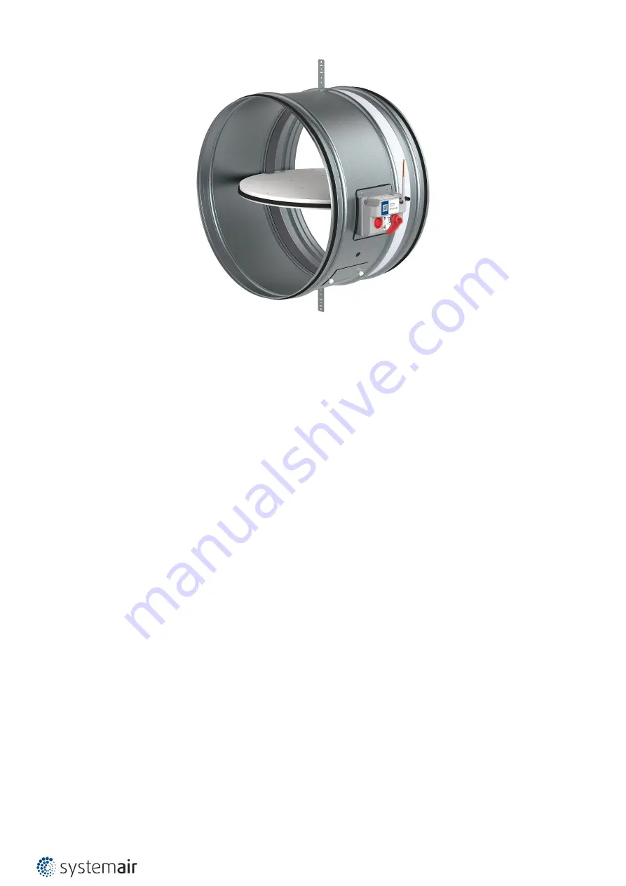
FDR-3G
Description
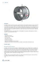
Fire dampers represent passive fire protection, designed with the help of compartmentalization to prevent the spread
of toxic gases, smoke and fire. Standard fire dampers are designed and certified in accordance with EN 15650 and
tested for EIS criteria according to EN 1366–2. Fire damper together with its installation form an inseparable part of fire
resistivity rating. FDR-3G fire dampers are designed for the installations listed and described in their User Manual. By
default, all fire dampers are supplied with a manual mechanism or actuator mechanism, optionally with a supply and
communication unit.
The activation mechanisms are removable and are interchangeable, for example an actuator operated mechanism
instead of a manually operated mechanism.
Highlights
• Lightweight construction
• Tightness class 3C as standard
• Low pressure drop
• Changeable mechanism
• Inspection opening built-in
• Great variety of installations rated up to EI120S
• Modulated actuator suitable for system balancing - possibility to open the blade at the desired angle.
Activation Types
Manually Operated Fire Dampers
By default, all manually operated fire dampers are supplied with manual control, optionally with micro switches and
electromagnets. In case of fire, the fire damper is closed automatically. Depending on the version, the damper closes
either after the melting of the thermal fuse or by means of remote activation through an electromagnet in impulse
connection. After the closing of the damper blade, it is mechanically locked in the closed position and can only be
opened manually. The actuating mechanism is activated when the temperature of the air in the duct reaches 74°C and
the damper closes within 10 seconds after the melting of the fuse.
•
H0
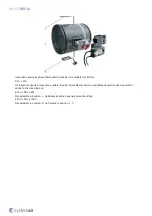
Fire damper with an activation mechanism with a cover, manual crank and with a spring return release mechanism
activated by a fusible thermal link set to 74°C (on demand 100°C).
•
H2
Summary of Contents for 163262
Page 1: ...FDR 3G Circular Fire Damper Handbook ...
Page 19: ...19 67 FDR 3G ...
Page 20: ...20 67 FDR 3G ...
Page 23: ...23 67 FDR 3G ...
Page 24: ...24 67 FDR 3G ...
Page 27: ...27 67 FDR 3G ...
Page 28: ...28 67 FDR 3G ...
Page 31: ...31 67 FDR 3G ...
Page 33: ...33 67 FDR 3G Notes ve Vertical wall 1 Smaller distances maximum resistivity EI90 ve i o S ...
Page 35: ...35 67 FDR 3G ...
Page 36: ...36 67 FDR 3G ...
Page 39: ...39 67 FDR 3G ...
Page 40: ...40 67 FDR 3G ...
Page 67: ...Systemair DESIGN 2022 07 11 Handbook_FDR_3G_en GB Original instructions ...


