34/67 |
FDR-3G
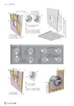
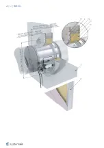
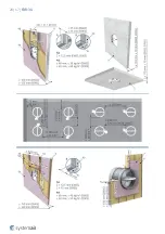
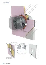
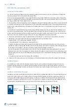
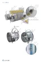
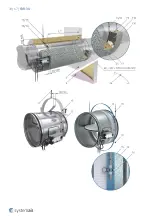
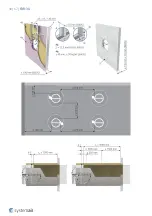
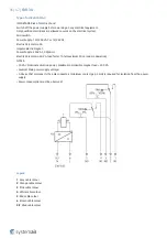
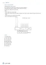
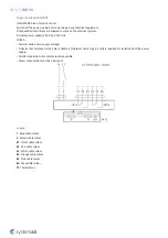
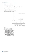
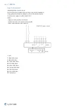
ON & OUT of the wall installation, EI90S
Using 2 layers of Mineral Wool
TIP: The duct-wall cavity filling can be also replaced by plaster/mortar/concrete (F2) as a replacement of filling (F9),
then the coating (F10) is not needed for the cavity filling.
There are two hanging possibilities, using ringlet MP-MX or using ringlet UVH30 see instructions point 3. Prepare the
damper for installation by fastening in the blade and perforation location with ceramic adhesive tape (12) and bind it
up using a suitable sheet metal ringlet (13 or 14)
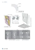
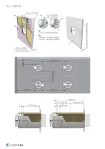
1. The supporting construction opening must be prepared as depicted. Opening surfaces must be even and cleaned off.
The flexible wall opening must be reinforced as per the standards for plasterboard walls. The opening dimensions are
driven by the nominal dimensions of the damper with added clearance. For circular dampers prepare the opening of
diameter D1.
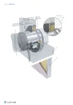
2. Insert the duct into the load-bearing structure along with the damper in such a way that the duct will stick out of
the wall to the needed distance. Press the insulation around the duct (F9) and cut its edges to even it with the wall
surface. Paint the insulation surface in alignment with the wall with a suitable coat of paint (F10) up to 100 mm from
the duct to cover the insulation and part of the wall. Or use as filling plaster/mortar/concrete (F2).
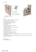
3. Attach the circular damper using L-shaped sheet metal consoles (F11) evenly across the perimeter at 4 points.
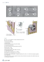
4. Depending on the used ringlet embedded in the blade location hang the damper onto:
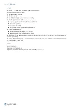
• threaded rod M12 (11) when using ringlet MP-MX (13).
• 2 × threaded rod M10 (15) when using ringlet UVH30 (14).
5. Insulate the damper and duct parts between the damper and the wall. Glue the insulation onto the wall using
suitable fire-resistive coating (BSF, ISOVER). Bind the circular damper part and duct insulation with a binding wire (9)
for both layers of insulation in the usual way that is applied when insulating circular ducts.
6. Cover the insulation face and perimeter up to 150 mm from the insulation edge using galvanized sheet metal
(accessory A2), secure the sheet against the damper housing through accessories holes (10). Any protruding screws
which could stand in the way of the blade during its opening need to be shortened so that they don’t prevent blade
movement.
7. If needed, uncover and clean the damper after installation.
8. Make sure the fixing screws are not interfering with the blade movement and check the damper’s functionality.
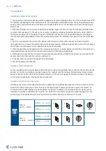
Installation Distances
For installation 5.1 ON & OUT, the minimum distance from the wall or ceiling to the damper body is 200 mm. For
multiple crossings through a fire-resistive wall the minimum distance between two damper bodies is 400 mm. A
distance of 200 mm applies for distances between the damper and a nearby foreign object crossing the fire-resistive
wall.
Installation in a Wall thinner than tested
Installation in a thinner wall is allowed under the condition that an additional layer/layers of fire protective board are
fixed to the surface of the wall in order to achieve the same length of damper penetration seal as was tested. The
minimum width of added boards around the damper is 200 mm. In addition, the alternative thinner wall should be
classified in accordance with EN 13501-2:2007 + A1: 2009 for fire-resistance required for product application. For a
protruding wall, the additional layers must be fixed on the steel supporting construction of the wall.
5.1
On, Out
FDR-3G
DN100 ... DN400
EI 60 (v
e
- i ↔ o) S
a)
b)
EI 90 (v
e
- i ↔ o) S
Summary of Contents for 163262
Page 1: ...FDR 3G Circular Fire Damper Handbook ...
Page 19: ...19 67 FDR 3G ...
Page 20: ...20 67 FDR 3G ...
Page 23: ...23 67 FDR 3G ...
Page 24: ...24 67 FDR 3G ...
Page 27: ...27 67 FDR 3G ...
Page 28: ...28 67 FDR 3G ...
Page 31: ...31 67 FDR 3G ...
Page 33: ...33 67 FDR 3G Notes ve Vertical wall 1 Smaller distances maximum resistivity EI90 ve i o S ...
Page 35: ...35 67 FDR 3G ...
Page 36: ...36 67 FDR 3G ...
Page 39: ...39 67 FDR 3G ...
Page 40: ...40 67 FDR 3G ...
Page 67: ...Systemair DESIGN 2022 07 11 Handbook_FDR_3G_en GB Original instructions ...

