65/67 |
FDR-3G
Operation Manual
Warning
To avoid injury, make sure to wear gloves and keep the blades movement area clear while manipulating with the
damper.NEVER OPEN THE INSPECTION LID WHEN THERE IS AIR FLOWING IN THE DUCT CONNECTED TO THE FIRE DAMPER!
Fire Damper Functionality Check
Manually Operated Activation Mechanism
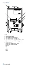
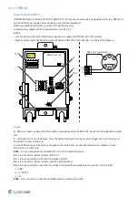
1.Open the damper - turn the red crank (P10) using a hexagon bent wrench No. 10 (P13). Turn the red crank so that
the indicator arrow is pointing to the “OPEN“ position (P11), the red crank needs to remain in the “OPEN“ position, and
the microswitch for the open position indication must be pushed (if installed).2.Close the damper – release the
mechanism by pressing the red release button (P9), the red crank will adjust its indicator arrow pointing to the
“CLOSED“ position (P12) and remain locked in this position, the microswitch for the closed position indication must be
pushed (if installed).3.Open the damper - turn the red crank (P10) using a hexagon bent wrench No. 10. (P13) Turn
the red crank so that the indicator arrow is pointing to the “OPEN“ position, the red crank needs to remain in the
“OPEN“ position, and the microswitch for the open position indication must be pushed (if installed).
Spring Return Actuator Operated Activation Mechanism
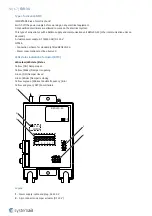
1.The fire damper must open automatically after the actuator circuit closes – the arrow on the actuator axis must show
the position 90°.2.Press the control switch (P9) on the Thermoelectric fuse and hold it until the fire damper is fully
closed – the arrow on the actuator axis must show the position 0°.3.Release the control switch on the Thermoelectric
fuse. The fire damper must become fully open – the arrow on the actuator axis must show the position 90° - which is
the operating position.
Operation Manual
After installation, it is necessary to adjust the damper into its operating position – open the fire damper.
Spring Return Actuator Operated Activation Mechanism
Connect the electric driving mechanism to the relevant electric power supply (see Electrical connection section). The
electromotor is activated and adjusts the damper into its open position.
Manually Operated Activation Mechanism
Turn the red crank into the “OPEN“ position. The damper blade must remain in open position.
Damper Inspection
The activation mechanism keeps the dampers on stand-by during their entire life cycle in accordance with this manual
issued by the manufacturer. It is not permitted to alter the dampers in any way nor perform any changes to their
structure without the manufacturer’s consent. The operator performs regular checks of the dampers as per established
regulations and standards at least once every 12 months. The check needs to be performed by an employee who has
been specifically trained for this purpose. The current fire damper condition determined during the inspection needs to
be entered into the operating logbook along with the date of the inspection, the legible name, surname and signature
of the employee who performed the inspection. The Operating Journal includes a copy of the employee’s
authorization. If any discrepancies are discovered, these need to be entered in the Operating Journal along with a
proposal for their removal. The Operating Journal can be found in product documents section. Immediately after the
installation and activation of the damper, it needs to be checked under the identical conditions as apply to the above
mentioned 12-month inspections. The visual check ensures that visible damages on the inspected damper parts are
seen. On its external side, the damper housing and the activation mechanism are checked. Due to the need to perform
a visual check of the damper’s internal parts, open the inspection lid. For small sizes there is the possibility of
removing the mechanism to perform the inspection. The removable mechanism always needs to be replaced into the
damper with the damper blade being closed. The damper’s internal casing, thermal fuse, seals, foaming substance, the
damper blade condition and accuracy of its closure during its leaning against the backstop in the closed position must
all be checked. There must not be any strange objects or a layer of impurities from the air distribution systems inside
the damper.
Summary of Contents for 163262
Page 1: ...FDR 3G Circular Fire Damper Handbook ...
Page 19: ...19 67 FDR 3G ...
Page 20: ...20 67 FDR 3G ...
Page 23: ...23 67 FDR 3G ...
Page 24: ...24 67 FDR 3G ...
Page 27: ...27 67 FDR 3G ...
Page 28: ...28 67 FDR 3G ...
Page 31: ...31 67 FDR 3G ...
Page 33: ...33 67 FDR 3G Notes ve Vertical wall 1 Smaller distances maximum resistivity EI90 ve i o S ...
Page 35: ...35 67 FDR 3G ...
Page 36: ...36 67 FDR 3G ...
Page 39: ...39 67 FDR 3G ...
Page 40: ...40 67 FDR 3G ...
Page 67: ...Systemair DESIGN 2022 07 11 Handbook_FDR_3G_en GB Original instructions ...

