background image

53/64 | 

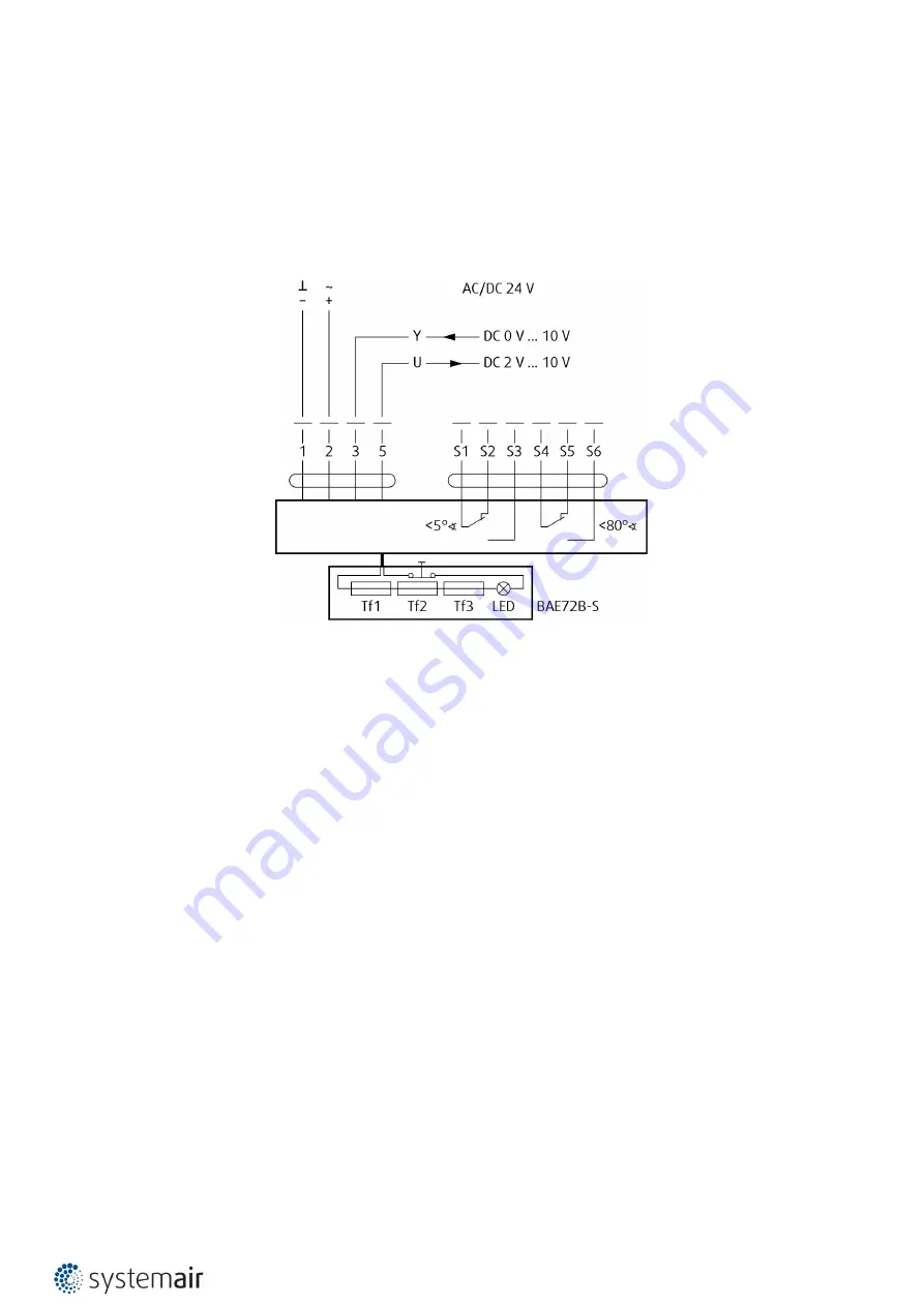
F-B90

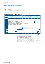
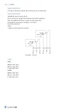
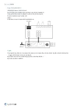
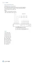
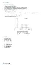
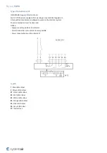
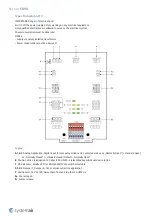
Type of Activation B24T-SR

IMPORTANT: Danger of electric shock!
Switch off the power supply before working on any electrical equipment.
Only qualified electricians are allowed to work on the electrical system.
Power consumption must be observed.
NOTES:
• Supply via safety isolation transformer.
• Power consumption must be observed!

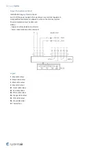
Legend

1

  Blue cable colour

2

  Brown cable colour

3

  White cable colour

5

  Orange cable colour

S1

  Violet cable colour

S2

  Red cable colour

S3

  White cable colour

S4

  Orange cable colour

S5

  Pink cable colour

S6

  Grey cable colour

Tf

  Thermal fuse

Summary of Contents for 178818

Page 1: ...F B90 Multiblade Fire Damper Handbook...

Page 2: ...2 64 F B90 Table of Contents Overview 3 Technical Parameters 6 Diagrams 8 Dimensions 14 Ordering Code 18 Product Handling 20 Installation 25 Electrical Parameters 46 Operation Manual 60...

Page 3: ...lling not visible Available with smoke detection One sided duct connection ended with Grille Fire Resistivity F B90 fire dampers are CE certified following the Construction Products Regulation accordi...

Page 4: ...he desired angle BSD230T or GSD230T Only for Grille types 11 and 22 GSD230T not available for sizes H 250 Overflow fire damper with Smoke Detector fitted activation mechanism 230V AC with a Belimo or...

Page 5: ...g device with test button P5 Sheet metal grille P6 Threaded inserts for duct connection P7 Threaded inserts for the grille P8 Mechanism cover P9 Product label P10 Smoke sensor ORS 144 K Hekatron P11 S...

Page 6: ...tures must be 20 C 50 C Relative humidity Less than 95 3K5 EN 60721 3 3 Product protected from Weather rain and water from other sources Condensation Cannot form on the product Icing Cannot form on th...

Page 7: ...Nominal activation conditions sensitivity Pass Response delay response time Closure wihin period of 2 minutes Operational reliability Manual 50 cycles Motorized 10200 cycles and 10000 cycles modulated...

Page 8: ...p A weighted sound power level in dB A 1000 2000 5000 m h 500 1000 2000 l s 5 10 50 Pa W 200 H 500 W 400 H 500 W 600 H 500 W 800 H 500 25 30 35 40 45 50 55 25 30 35 40 45 50 55 60 25 30 35 40 45 50 55...

Page 9: ...50 55 25 30 35 40 45 50 55 60 25 30 35 40 45 50 55 60 25 30 35 40 45 50 55 F B90 00 Pressure drop A weighted sound power level in dB A 2000 5000 10000 m h 500 1000 2000 l s 5 10 20 Pa W 200 H 750 W 4...

Page 10: ...40 45 50 55 25 30 35 40 45 50 55 60 25 30 35 40 45 50 55 60 25 30 35 40 45 50 55 F B90 01 Pressure drop A weighted sound power level in dB A 2000 5000 10000 m h 500 1000 2000 l s 5 10 20 Pa W 200 H 7...

Page 11: ...0 45 50 55 25 30 35 40 45 50 55 60 25 30 35 40 45 50 55 60 65 25 30 35 40 45 50 55 F B90 01 Pressure drop A weighted sound power level in dB A 2000 5000 10000 m h 500 1000 2000 l s 5 10 50 Pa W 200 H...

Page 12: ...0 45 50 55 25 30 35 40 45 50 55 60 25 30 35 40 45 50 55 60 65 25 30 35 40 45 50 55 F B90 11 Pressure drop A weighted sound power level in dB A 1000 5000 10000 m h 500 1000 2000 l s 5 10 20 Pa W 200 H...

Page 13: ...40 45 50 55 25 30 35 40 45 50 55 60 25 30 35 40 45 50 55 60 65 25 30 35 40 45 50 55 F B90 11 Pressure drop A weighted sound power level in dB A 1000 5000 10000 m h 500 1000 2000 l s 5 10 50 Pa W 200...

Page 14: ...0 287 0 320 0 354 0 360 0 387 0 407 0 421 0 454 0 461 0 488 0 521 1000 0 099 0 118 0 137 0 156 0 176 0 199 0 214 0 226 0 253 0 256 0 291 0 330 0 368 0 407 0 414 0 445 0 468 0 484 0 522 0 530 0 561 0...

Page 15: ...15 64 F B90 Dimensions W W 20 H H 20 W 222 H 40 H 50 W 230 145 125 10 141 10 10 2 mm F B90 NOTE Inclusive grille...

Page 16: ...4 7 15 1 15 5 15 9 16 0 16 6 16 7 17 4 18 2 18 9 20 0 20 1 20 8 21 3 21 5 22 3 22 4 23 1 23 8 13 7 14 0 14 4 14 8 15 2 15 6 16 0 16 1 16 7 16 8 17 5 18 3 19 0 19 8 20 5 21 2 21 7 21 9 22 7 22 8 23 5 2...

Page 17: ...1 2 1 3 1 3 1 4 1 4 1 4 1 5 500 0 8 0 8 0 9 0 9 1 0 1 0 1 0 1 1 1 1 1 1 1 2 1 3 1 3 1 4 1 4 1 5 1 5 1 6 1 7 1 7 1 7 1 8 625 0 9 1 0 1 0 1 1 1 1 1 2 1 2 1 2 1 3 1 3 1 4 1 5 1 6 1 7 1 7 1 8 1 8 1 9 2 0...

Page 18: ...Actuator B24T 24V AC DC Belimo Actuator BST0 230V AC Supply comm unit 24V AC DC Belimo Actuator B24T SR 24V AC DC Belimo Actuator modulated 0 10 V G230T 230V AC Gruner Actuator G24T 24V AC DC Gruner A...

Page 19: ...19 64 F B90 Example of the Ordering Code F B90 315 375 00 B230T Multiblade fire damper with width of 315 mm and height of 375 mm without a grille Activated by a 230 V Belimo actuator...

Page 20: ...place Fix the mechanism cover by previously removed screws 4 Placing the damper Prepare the opening and or duct connection surfaces as per the desired installation type Carefully lift the damper with...

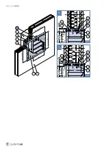
Page 21: ...21 64 F B90 5 1 1 2 B A1 A2 3 A1 B A2...

Page 22: ...22 64 F B90 C1 C2 C3 C4 C5 i D 4 1 8 1 Fx D1 D2...

Page 23: ...23 64 F B90 F3 5 2 E F F3 E1 E2 5 F1 F2 6...

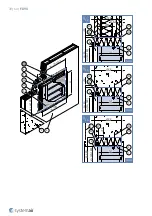
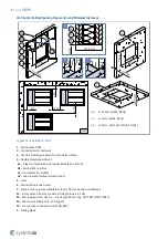
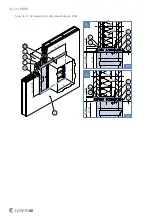
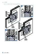
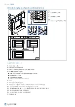
Page 24: ...Connected sheet metal ductwork tested according to EN 1366 8 or EN 1366 9 3 Filling 5 Grille 8 Support brick metal delivery or wood stud not part of damper Fx Filling per chosen installation F3 Self t...

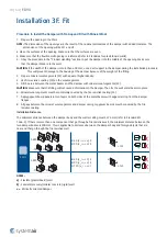
Page 25: ...a 125 b 125 3 Soft F B90 00 01 02 EI 60 ve ho i o S EI 90 ve ho i o S a 125 b 125 c 125 620 kg m3 F B90 11 22 EI 60 ve i o S EI 90 ve i o S EI 120 ve i o a 125 b 125 3F Fit F B90 00 01 02 EI 60 ve i...

Page 26: ...partition structure do a check of the damper blades Make sure that the damper blades in its closed position are in this structure There is a gap between the fire damper and the wall or ceiling opening...

Page 27: ...of the damper do not become dirty If they become dirty they will not operate correctly a To prevent damage cover the primary parts during filing installation b To prevent leakage of the filling mater...

Page 28: ...ll Max Resistivity EI90S 125 50 50 141 H 1 W 1 12 5 125 50 50 12 5 141 125 50 141 125 50 141 H 1 W 1 H 1 W 1 H 1 W 1 H W H W H W H W H 1 H 100 W1 W 280 W H Y3 mm F3 1 F1 F2 Y1 mm F3 1 F1 F2 Y4 mm F3 1...

Page 29: ...141 12 5 125 50 50 12 5 141 125 50 141 125 50 141 H 1 W 1 H 1 W 1 H 1 W 1 H 1 W 1 H W H W H W H W H 1 H 100 W1 W 280 H W Y7 mm F3 1 F1 F2 F1 F2 Y5 mm 5 F3 1 5 2 Y8 mm F3 1 F1 F2 F1 F2 Y6 mm 5 F3 1 5...

Page 30: ...30 64 F B90 Types 00 Installed in the Ceiling Floor Max Resistivity EI90S 125 50 141 125 50 141 H1 W1 H1 W1 W1 W 280 H1 H 100 Y16 Y15 mm mm F3 1 2 F2 F1 2 F2 F1 F3 1 1 F1 3 2 Y H W H W H W Y...

Page 31: ...11 22 Installed in the Wall Max Resistivity EI90S EI120 125 50 50 12 5 141 50 141 125 50 141 H 1 W 1 H 1 W 1 H 1 W 1 125 H W H W H W H 1 H 100 W1 W 280 H W F1 Y9 mm F3 1 5 F1 Y11 mm F3 1 5 F1 Y10 mm F...

Page 32: ...F B90 125 50 12 5 141 50 H 1 W 1 125 141 50 H 1 W 1 125 141 50 H 1 W 1 H W 180 H W 180 H W 180 H 1 H 100 W1 W 280 W 180 H F3 1 5 F1 F2 Y12 mm F3 1 5 F1 F2 Y13 mm 6 6 F3 1 5 F1 F2 Y14 mm 7 6 6 1 F1 3...

Page 33: ...metal ductwork 3 Concrete masonry cellular concrete wall or ceiling 4 Flexible plasterboard wall 4a 2 layers of plasterboard fireproof plate type F EN 520 4b Vertical CW profiles 4c Horizontal CW pro...

Page 34: ...etween the wall and the damper with mineral wool segments F4 CAUTION Make sure that the filling will not cause deformation to the damper 6 Use fire resistive coating F5 on the wool segments and the wa...

Page 35: ...vity EI90S 125 50 50 141 H 1 W 1 12 5 10 125 50 50 12 5 10 141 125 50 141 10 125 50 10 141 H 1 W 1 H 1 W 1 H 1 W 1 H W H W H W H W H 1 H 100 W1 W 280 W H 3 4 2 1 F4 F5 Y Y3 mm F3 1 F4 F5 F2 Y1 mm F3 1...

Page 36: ...25 50 50 12 5 10 141 125 50 141 10 125 50 10 141 H 1 W 1 H 1 W 1 H 1 W 1 H 1 W 1 H W H W H W H W W1 W 280 H 1 H 100 H W Y7 mm F3 1 F4 F5 F2 F4 F2 Y5 mm 5 F3 1 F5 5 2 Y8 mm F3 1 F4 F5 F2 F4 F2 Y6 mm 5...

Page 37: ...64 F B90 Types 00 Installed in the Ceiling Floor Max Resistivity EI90S 125 50 141 10 125 50 10 141 H1 W1 H1 W1 W1 W 280 H1 H 100 Y16 Y15 mm mm F3 F5 1 2 F2 F4 2 F2 F4 F3 F5 1 1 F5 F4 3 2 Y Y H W H W H...

Page 38: ...led in the Wall Max Resistivity EI90S EI120 125 50 50 12 5 10 141 50 141 125 50 10 141 H 1 W 1 H 1 W 1 H 1 W 1 125 H W H W H W H 1 H 100 W1 W 280 H W F4 Y9 mm F3 1 F5 5 F4 Y11 mm F3 1 F5 5 F4 Y10 mm F...

Page 39: ...0 12 5 141 10 50 H 1 W 1 125 141 10 50 H 1 W 1 125 141 50 H 1 W 1 H W 180 H W 180 H W 180 H 1 H 100 W1 W 280 W 180 H 6 1 F4 F5 3 4 5 Y F3 1 F5 5 F4 Y12 mm F3 1 F5 5 F4 Y13 mm 6 6 1 F5 5 Y14 mm 7 6 F2...

Page 40: ...ete masonry cellular concrete wall or ceiling 4 Flexible plasterboard wall 4a 2 layers of plasterboard fireproof plate type F EN 520 4b Vertical CW profiles 4c Horizontal CW profiles 4d Mineral wool t...

Page 41: ...he area between the metal beams and the damper with mineral wool segments F4 CAUTION Make sure that the filling will not cause deformation to the damper Than fix the wall metal beams in place 6 Minera...

Page 42: ...0 Types 00 01 02 Installed in the Wall Max Resistivity EI90S 125 50 20 141 H 1 W 1 12 5 10 125 50 12 5 10 141 H 1 W 1 H W H W 20 W H H 1 H 40 W1 W 222 Y2 mm F3 1 F4 F5 F2 Y1 mm F3 1 F4 F5 F2 2 2 Y 2 1...

Page 43: ...43 64 F B90 125 50 20 141 H 1 W 1 12 5 10 125 50 12 5 10 141 H 1 W 1 H W H W 20 H W H 1 H 40 W1 W 222 Y4 mm F3 1 F4 2 F2 Y3 mm F3 1 F4 F5 F2 2 F5 5 5 Y 2 1 F4 F5 4 5 Y...

Page 44: ...e Wall Max Resistivity EI90S EI120 125 50 12 5 10 141 H 1 W 1 H W 20 125 50 20 141 H 1 W 1 12 5 10 H W 180 H W H 1 H 40 W1 W 222 W 180 H H 1 H 40 W1 W 222 Y5 mm F3 1 F4 F5 F2 5 Y5 1 F4 F5 4 5 Y6 6 1 F...

Page 45: ...lular concrete wall or ceiling 4 Flexible plasterboard wall 4a 2 layers of plasterboard fireproof plate type F EN 520 4b Vertical CW profiles 4c Horizontal CW profiles 4d Mineral wool thickness cubic...

Page 46: ...BFL24 T ST BKN230 24 B24T SR AC 50 60 Hz DC 24 V 6 5 VA BFL24 SR T BSD230T AC 230 V 50 60 Hz 11 VA BFL24 T ST BKN230 24 C MP ORS144K BSD24T AC 230 V 50 60 Hz 6 VA BFL24 T ORS144K B230T AC 230 V 50 60...

Page 47: ...z 11 VA 340TA 024 05 ST01 BKN230 24 C MP ORS144K GSD24T AC 50 60 Hz DC 24 V 11 VA 340TA 024 05 ORS144K G230T AC 230 V 50 60 Hz 11 5 VA 360TA 230 12 G24T AC 50 60 Hz DC 24 V 7 VA 360TA 024 12 GST0 AC 5...

Page 48: ...48 64 F B90 Wire preparation C1 A1 A2 B C2 C2 H B G A1 A2 B 2 1 C2 C1...

Page 49: ...supply before working on any electrical equipment Allow only qualified electricians to work on the electrical system Microswitch Power Supply AC 125 250 V or DC 12 24 V Electric Parameters 3A NOTES S...

Page 50: ...on Main power supply voltage A device that disconnects the pole conductors minimum contact gap 3 mm is required for isolation from the power supply Paralell connection of several actuators possible Po...

Page 51: ...S Supply via safety isolation transformer Paralell connection of several actuators possible Power consumption must be observed Legend 1 Blue cable colour black for BF24 T 2 Red cable colour white for...

Page 52: ...work on the electrical system Power consumption must be observed NOTES Connection scheme for standardly fitted BKN230 24 Legend 1 Jumper factory fitted Can be removed if necessary to be replaced by a...

Page 53: ...to work on the electrical system Power consumption must be observed NOTES Supply via safety isolation transformer Power consumption must be observed Legend 1 Blue cable colour 2 Brown cable colour 3 W...

Page 54: ...served NOTES Caution Main power supply voltage A device that disconnects the pole conductors minimum contact gap 3 mm is required for isolation from the power supply Paralell connection of several act...

Page 55: ...rk on the electrical system Power consumption must be observed NOTES Supply via safety isolation transformer Paralell connection of several actuators possible Power consumption must be observed Legend...

Page 56: ...n must be observed Legend A1 A2 Analog Application Digital input for manual override can be selected via bus as Normally Open standard open or Normally Closed standard closed Default Normally Open B P...

Page 57: ...to work on the electrical system Power consumption must be observed NOTES Supply via safety isolation transformer Power consumption must be observed Legend 1 Blue cable colour 2 Brown cable colour 3...

Page 58: ...on any electrical equipment Only qualified electricians are allowed to work on the electrical system Power consumption must be observed NOTES Caution Main power supply voltage A device that disconnect...

Page 59: ...on the electrical system Power consumption must be observed NOTES Supply via safety isolation transformer Legend 1 Blue cable colour 2 Brown cable colour S1 Violet cable colour white for BF24 T S2 Re...

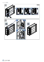
Page 60: ...utton P13 This will close the damper Spring return actuator activation mechanism By pressing and holding the test button on the thermal fuse P13 This will close the damper Note When you release the te...

Page 61: ...61 64 F B90 D1 D2 D3 P13 P13 E E H B G 1 2 H...

Page 62: ...ts or layers of contamination in the air distribution systems of the damper The internal casing of the damper The sealings The foaming material The condition of the damper blade How accurately the dam...

Page 63: ...F B90 Supplement If you find differences from the terms and the technical specifications that are in this manual speak to the manufacturer We reserve the right to make changes to the product without n...

Page 64: ...Systemair DESIGN 2021 08 25 Handbook_F_B90_en GB...

Reviews: