Annex
10—5
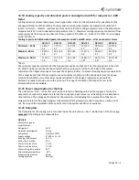
10.20
Cooling
capacity
and
absorbed
power
consumption
in
kW
for
compressor
‐
EER
factor
Cooling
capacity
and
absorbed
power
consumption
data
is
listed
in
the
table
below
for
calculation
of
the
energy
performance
of
the
building.
Cooling
capacity
and
absorbed
power
consumption
are
listed
for
3
levels
–
minimum
–
medium
–
and
maximum
revolutions
for
the
cooling
compressor
when
the
evaporation
temperature
is
10
°C
and
condensation
temperature
is
50
°C.
Maximum
cooling
capacity
at
nominal
air
flow
when
supply
air
flow
is
equal
to
exhaust
air
flow,
outdoor
28
°C/50%
r.H.,
indoor
25
°C/50%
r.H.
and
supply
air
18
°C/90%
r.H..
Cooling
capacity
in
kW/absorbed
power
consumption
in
kW
and
EER
‐
value
–
all
at
nominal
air
volume
DVU
‐
10
DVU
‐
15
DVU
‐
20
DVU
‐
25
DVU
‐
30
DVU
‐
40
Minimum
–
35
Hz
5.6/1.2
‐
4.5
7.7/1.9
‐
4.1
11.5/2.2
‐
5.2
15.7/3.3
‐
4.7
18.5/3.8
‐
4.9
23.2/4.5
‐
5.1
Medium
–
60
Hz
8.9/2.3
‐
3.8
12.4/3.4
‐
3.7
18.5/4.3
‐
4.4
27.5/7.1
‐
3.9
29.6/7.1
‐
4.2
39.7/9.4
‐
4.2
Maximum
–
90
Hz
11.1/3.7
‐
3.0
15.7/5.4
‐
2.9
23.3/6.9
‐
3.4
33.8/11.1
‐
3.0*
36.7/11.3
‐
3.2*
47.3/13.2
‐
3.6
*85
Hz
The
minimum
capacity
is
selected
at
the
frequency
converter
output
at
35
Hz
(the
compressor
in
the
DVU
20,
25/30
and
40
can
reduce
the
capacity
further
to
even
lower
revolutions
at
30
Hz).
At
the
lowest
revolutions
the
hotgas
valve
opens
to
reduce
the
capacity
further
–
the
lowest
cooling
capacity
equals
10
%
of
the
capacity
at
90
Hz.
If
the
temperature
and
humidity
conditions
on
the
site
deviate
from
the
above
‐
mentioned
conditions,
accurate
values
can
be
calculated
in
the
design
programme
SystemairCAD.
Systemair
is
ready
to
provide
you
with
a
‐
out,
if
a
copy
of
calculation
of
the
specific
unit
in
the
SystemairCAD
is
not
available.
10.21
Power
consumption
for
the
fans
The
unit
section
‐
DVU
‐
is
one
of
several
sections
in
the
air
handling
unit,
and
the
supply
air
fan
for
the
evaporator
as
well
as
the
exhaust
air
fan
for
the
condenser,
heat
recovery
and
heating
coil
are
installed
in
other
sections.
The
energy
performance
for
the
complete
unit
including
the
consumption
of
the
fans
is
always
calculated
in
the
design
programme
SystemairCAD.
Systemair
is
ready
to
provide
you
with
a
‐
out,
if
a
copy
of
the
calculation
of
the
specific
unit
in
the
SystemairCAD
is
not
available.
10.22
Data
plate
The
data
plate
for
the
cooling
unit
is
mounted
inside
the
unit
section
–
DVU
–
behind
one
of
the
doors.
An
example
of
the
data
plate
is
shown
below.
DVU
‐
40
Manufaturing
year
Serial
Number:
Refrigerant
407C
Quantity
of
refrigerant
9.8
kg
Compressor
Danfoss
VTZ171
Supply
voltage
3*400
V
+
N
+
PE
Running
load
ampere
31.5
A
Main
circuit
breaker
35
A
Short
circuit
level
min
1,0
kA
Short
circuit
level
max
7,3
kA
Max
working
temperature
55°C
Min
working
temperature
‐
40°C
Max
working
pressure
26
bar
Testing
pressure
28.6
bar
Summary of Contents for Danvent DV
Page 28: ...Bilag 8 8...
Page 33: ...Annex 9 5...
Page 36: ...Annex 9 8 9 3 Assemble divided rotor for DV 60 DV 80 DV 100 DV 120 og DV 150...
Page 37: ...Annex 9 9...
Page 38: ...Annex 9 10...
Page 39: ...Annex 9 11...
Page 40: ...Annex 9 12...
Page 41: ...Annex 9 13...
Page 42: ...Annex 9 14...
Page 43: ...Annex 9 15...
Page 44: ...Annex 9 16...
Page 45: ...Annex 9 17...
Page 46: ...Annex 9 18...
Page 47: ...Annex 9 19 9 4 Assemble divided rotor for DV 190 og DV 240...
Page 48: ...Annex 9 20...
Page 49: ...Annex 9 21...
Page 50: ...Annex 9 22...
Page 51: ...Annex 9 23...
Page 52: ...Annex 9 24...
Page 53: ...Annex 9 25...
Page 54: ...Annex 9 26...
Page 55: ...Annex 9 27...
Page 56: ...Annex 9 28...
Page 57: ...Annex 9 29...
Page 58: ...Annex 9 30...
Page 71: ...Annex 12 3...
Page 75: ...Annex 12 7...


