background image

English

IOM KOG 04-N-3

ALL

Part number / Code / Teil Nummer / Codice / Código : 

3990676

Supersedes / Annule et remplace / Annulliert und ersetzt / 
Annulla e sostituisce / Anula y sustituye : 

IOM KOG 04-N-2

ALL

Français

Español

Deutsch

Italiano

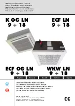
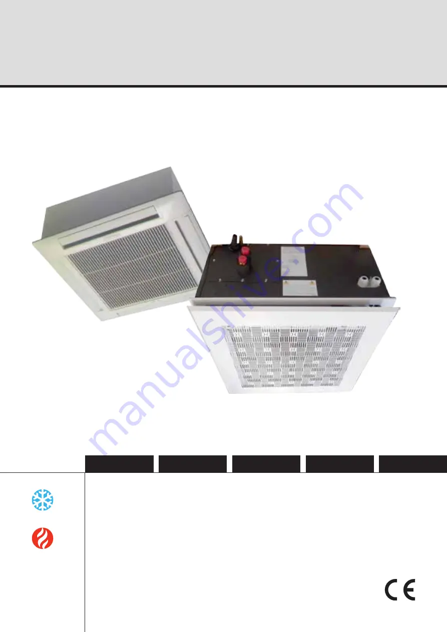
CHILLED OR HEATED WATER CASSETTE
CASSETTE EAU GLACEE OU EAU CHAUDE
KALTWASSER ODER GEHEIZTESWASSER -KASSETTE
CASSETTA ACQUA GHIACCIATA O RISCALDATA
CASETE AGUA HELADA O CALENTADA

Installation and maintenance manual

Manuel d’installation et de maintenance

Installations- und Wartungshandbuch

Manuale di installazione e di manutenzione

Manual de instalación y de mantenimiento

IOM KOG 04-N-3

Part number / Code / Teil Nummer / Codice / Código : 

3990676

Supersedes / Annule et remplace / Annulliert und ersetzt / 
Annulla e sostituisce / Anula y sustituye : 

IOM KOG 04-N-2

K OG LN

9 ÷ 18

ECF OG LN

ECF LN

WKW LN

9 ÷ 18

9 ÷ 18

9 ÷ 18

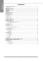
Summary of Contents for ECF LN 9 2P

Page 1: ...ZTESWASSER KASSETTE CASSETTA ACQUA GHIACCIATA O RISCALDATA CASETE AGUA HELADA O CALENTADA Installation and maintenance manual Manuel d installation et de maintenance Installations und Wartungshandbuch...

Page 2: ......

Page 3: ...INSTALLATION INSTRUCTION NOTICE D INSTALLATION INSTALLATIONSHANDBUCH ISTRUZIONI INSTALLAZIONE INSTRUCCIONES DE INSTALACI N...

Page 4: ...ATER 12 13 REGULATION 13 13 1 THERMOSTAT LOCATION 13 13 2 CONTROL 13 13 2 1 INFRA RED VERSION INFRA RED REMOTE CONTROL 13 13 2 2 ROOM THERMOSTAT TRM VP AND TRM FA 15 13 2 3 TAE20 ROOM THERMOSTAT 17 14...

Page 5: ...handled using lifting and handling equipment appropriate to the unit s size and weight Any wiring produced on site must comply with the corresponding national electrical regulations Make sure that the...

Page 6: ...ts are delivered fully assembled factory tested and ready to operate Any modification to the units without the manufacturer s prior approval shall automatically render the warranty null and void The f...

Page 7: ...h heating without heating Nominal current A 6 7 0 3 8 0 3 10 8 0 4 Fuse rating gG A 10 1 10 1 16 1 Fuse rating ASE VDE A 16 2 16 2 16 2 Power supply 230V 50Hz 230V 50Hz 230V 50Hz 230V 50Hz 230V 50Hz 2...

Page 8: ...to be installed ideally in the place of a suspended ceiling tile panels dimensions of 60 x 60 cm or multiples thereof in a ceiling with a minimum height of 2 5 metres and of 4 metres maximum Do not i...

Page 9: ...the insulating foam from around the mounting nuts The possibility of fitting the angle attachment fittings at different heights leaves the installer the choice of mounting them on the cassette in the...

Page 10: ...ensation insulation material 6 mm thick expanded polystyrene or expanded neoprene Fireproofing classification M1 IF THE ABOVE INSTRUCTIONS ARE NOT FOLLOWED CONDENSATE LEAKS MAY OCCUR Distributing air...

Page 11: ...ry to ensure that the appliance operates correctly The installation and operating conditions require the MANDATORY fitting of a valve ON the unit OR AND upstream in the hydraulic circuit This is to pr...

Page 12: ...Cables capacity to transport the total system current draw Short circuit protection shall be provided This protection shall comprise fuses or circuit breakers with high breaking capacity mounted on t...

Page 13: ...ith hot water in winter or with chilled water in summer and during the mid season periods A 3 way valve must be installed on the water circuit supplying the unit Summer and mid season The 3 way valve...

Page 14: ...ric heating system is equipped with 2 SAFETY DEVICES One is reset automatically the other is manually reset They cut off electrical supply to the heating resistances as soon as an operating anomaly is...

Page 15: ...t it is not located in shelving or covered by curtains Any source of parasitic heat negatively influences temperature regulation accuracy Therefore avoid the sun s rays or proximity to portable heatin...

Page 16: ...display I FEEL sensor Infrared signal transmitter ROOMkey displayoftheambienttemperature LOCK key SET key Press for 5 seconds to set the time RESET FUNCTION 1 Remove one battery 2 Simultaneously pres...

Page 17: ...itch 0 I ON I OFF 0 Medium speed High Speed Lown Speed Linear switch Linear switch COOLING HEATING 13 2 2 3 DIMENSIONS 13 2 2 4 ELECTRICAL CONNECTIONS Connection of the thermostat TRM VP and TRM FA Co...

Page 18: ...nob for reducing the temperature range Example 12 C to 25 C 13 2 2 7 2 ADJUSTEMENT PROCEDURE 1 Setting the temperature range e g max 25 C min 12 C 2 Remove the control knob 3 Use a pointed object to a...

Page 19: ...rew terminal connections are located on the mounting plate with the DIP switches on the back of the case 13 2 3 3 ADJUSTEMENT AND CONTROL ELEMENTS 1 Operating mode switch ON OFF and manual fan speed s...

Page 20: ...action the frame should be correctly centered in relation to the false ceiling and it should especially ensure an airtight separation between air succion and air discharge The seals are illustrated in...

Page 21: ...R INSTALLATION Place the air intake grille hinges in the openings rep A Install the filter in the location provided rep B Close the grille with the locks on both sides 14 2 1 PLASTIC FACADE 14 2 2 DIF...

Page 22: ...without any signs of leaks or air bubbles When ethylene glycol anti freeze is used check that the concentration level is correct 3 Check that the water quality complies with the indicated standards 4...

Page 23: ...thermal efficiency of the unit and irreversible damage to the equipment The manufacturer and its representative decline all responsability in the event of untreated or incorrectly treated water being...

Page 24: ...he complete installation in service 19 1 1 CASING 1 Clean the outer panels 2 Remove the panels 3 Check that the insulation is not damaged Repair as required 19 1 2 CONDENSATE DRAIN PAN 1 Check that th...

Page 25: ...ed regularly Cleaning intervals vary depending on the amount of impurities in the air to be conditioned It is recommended that the filter is replaced at regular intervals A dirty filter creates a decr...

Page 26: ...24...

Page 27: ...INSTALLATION INSTRUCTION NOTICE D INSTALLATION INSTALLATIONSHANDBUCH ISTRUZIONI INSTALLAZIONE INSTRUCCIONES DE INSTALACI N...

Page 28: ...U THERMOSTAT 13 13 2 RAPPEL DE COMMANDE 13 13 2 1 UNITE INFRAROUGE TELECOMMANDE INFRAROUGE 13 13 2 2 THERMOSTATS D AMBIANCE TRM VP OU TRM FA 15 13 2 3 THERMOSTAT D AMBIANCE TAE20 17 14 DIFFUSION DE L...

Page 29: ...L appareil doit tre manipul l aide de syst mes con us pour r sister son poids Tous les c blages utilisateur doivent tre r alis s conform ment la r glementation nationale correspondante Assurez vous qu...

Page 30: ...ent ne pas fonctionner correctement 3 GARANTIE Les unit s sont livr es enti rement assembl s essay s et pr ts fonctionner Toute modification sur les unit s sans accord crit du constructeur entra nera...

Page 31: ...7 0 3 8 0 3 10 8 0 4 Calibre fusible gG A 10 1 10 1 16 1 Calibre fusible ASE VDE A 16 2 16 2 16 2 Tension alimentation 230V 50Hz 230V 50Hz 230V 50Hz 230V 50Hz 230V 50Hz 230V 50Hz Section fil alimenta...

Page 32: ...fond dimensions des dalles 60 x 60 cm et multiples une hauteur minimum de 2 5 m tres et 4 m tres maximum N installez pas le caisson dans un local o sont entrepos s des gaz acides ou bases inflammables...

Page 33: ...la mousse isolante autour des crous de fixation La possibilit de r glage des corni res a diff rente hauteur laisse le choix l installateur de fixer les corni res en partie haute ou en partie basse de...

Page 34: ...installation est termin e toutes les surfaces des gaines non calorifug es doivent tre recouvertes de mati re isolante anti condensation polystyr ne expans n opr ne expans d une paisseur de 6 mm mini...

Page 35: ...u la circulation simultan e d eau glac e et d eau chaude dans un changeur 4 tubes La premi re mise en eau des cassettes pour v rification de l tanch it des circuits peut s effectuer de fa on temporair...

Page 36: ...DE MISE EN MARCHE ACCIDENTELLE DE L UNIT T O U T M A N Q U E M E N T A U X I N S T R U C T I O N S SUSMENTIONN ES PEUT ENTRA NER DES L SIONS GRAVES OU LA MORT PAR LECTROCUTION Si les commandes locales...

Page 37: ...en eau chaude l hiver soit en eau glac e l t et la mi saison Il est indispensable d installer une vanne 3 voies sur le circuit d eau alimentant l unit Et et mi saison Le thermostat agit sur la vanne 3...

Page 38: ...erie de chauffage lectrique est munie de 2 SECURITES une r armement automatique une r armement manuel qui coupent les r sistances chauffantes d s la d tection d une anomalie dans le fonctionnement La...

Page 39: ...e soit ni mont dans des rayonnages ou recouvert par des rideaux Toutes sources de chaleur parasites influencent n gativement la r gulation vitez donc le rayonnement solaire la proximit d appareils de...

Page 40: ...eure Afficheur cristaux liquides Capteur I FEEL Emetteur du signal infrarouge Touche ROOM affichage de la temp rature ambiante Touche VERROUILLAGE Touche SET appuyer pendant 5s pour r gler l heure FON...

Page 41: ...rrupteur lin aire ventilation moyenne ventilation rapide ventilation lente Interrupteur 0 I Marche I Arr t 0 Interrupteur lin aire froid chaud 13 2 2 3 DIMENSIONS 13 2 2 4 RACCORDEMENTS ELECTRIQUES Ra...

Page 42: ...mitation de la plage de temp rature Par exemple 12 25 C 13 2 2 7 2 PROCEDURE DE REGLAGE 1 D termination de la plage de temp rature exemple maxi 25 C mini 12 C 2 Enlever le bouton de r glage 3 Amener l...

Page 43: ...ncliquet Les raccordements des bornes vis se trouvent sur la plaque de montage les commutateurs DIP au dos du bo tier 13 2 3 3 ELEMENTS DE REGLAGE ET DE COMMANDE 1 Commutateur Marche Arr t et s lectio...

Page 44: ...n excessive le cadre doit tre bien centr par rapport au faux plafond et surtout il doit assurer une s paration herm tique entre l aspiration et le soufflage de l air Dans la figure sont indiqu s les j...

Page 45: ...ille d aspiration dans les ouvertures rep A Installer le filtre dans les emplacements pr vus rep B Fermer la grille avec les verrous sur les 2 c t s A B 14 2 MISE EN PLACE DU FILTRE 14 2 1 FACADE PLAS...

Page 46: ...air Lorsque de l antigel thyl ne glycol est utilis v rifier que sa concentration est correcte 3 V rifier que la qualit de l eau est conforme aux normes indiqu es 4 V rifier que le tuyau d vacuation de...

Page 47: ...par l interm diaire de votre repr sentant le plus proche Cette commande doit inclure le nom de la pi ce le num ro de la pi ce le num ro du mod le et le num ro de s rie du groupe concern Apr s inspecti...

Page 48: ...BAC DE RECUPERATION DES CONDENSATS 1 V rifier que les orifices et les conduits d vacuation ne sont pas bouch s 2 Eliminer la salet accumul e En fonction des contraintes d utilisation et des volutions...

Page 49: ...aspiration de la batterie air trait La fr quence du nettoyage varie sensiblement selon le degr d impuret s de l air climatiser Il est conseill de remplacer le filtre r guli rement Un filtre sale provo...

Page 50: ...24...

Page 51: ...INSTALLATION INSTRUCTION NOTICE D INSTALLATION INSTALLATIONSHANDBUCH ISTRUZIONI INSTALLAZIONE INSTRUCCIONES DE INSTALACI N...

Page 52: ...13 13 1 ANORDNUNG DES THERMOSTATS 13 13 2 FERNBEDIENUNG MIT THERMOSTAT 13 13 2 1 INFRAROT EINHEIT INFRAROT FERNBEDIENUNG 13 13 2 2 RAUMTHERMOSTATS TRM VP ODER TRM FA 15 13 2 3 RAUMTHERMOSTAT TAE20 17...

Page 53: ...m F rdern des Ger tes m ssen Systeme benutzt werden die seinem Gewicht entsprechen Alle Benutzer Verdrahtungen m ssen in bereinstimmung mit den jeweils geltenden Vorschriften des Landes hergestellt we...

Page 54: ...nktionieren Die Ger ten werden vollst ndig montiert geliefert sie wurden getestet und sind betriebsbereit Durch eine nderung an den Ger ten ohne schriftliche Zustimmung des Herstellers wird die Garant...

Page 55: ...Heizung mit Heizung Ohne Heizung mit Heizung Ohne Heizung Nennstrom A 6 7 0 3 8 0 3 10 8 0 4 Sicherung gG A 10 1 10 1 16 1 Sicherung SEV VDE A 16 2 16 2 16 2 Betriebsspannung 230V 50Hz 230V 50Hz 230V...

Page 56: ...ergr e von 60 x 60cm und Vielfaches in einer H he von mindestens 2 5 Meter und von 4 Meter maximal installiert werden Die Inneneinheit nicht in einem Raum installieren in dem entz ndliche Gase S uren...

Page 57: ...ttern entfernt werden Durch die M glichkeit die Befestigungswinkel auf verschiedene H hen einzustellen hat der Installateur die Wahl die Winkel oben oder unten an der Kassette anzubringen Durch die Be...

Page 58: ...einem kondensationshemmenden Isolierstoff berzogen werden Polystyrolschaum Neoprenschaum 6 mm dick Brandklasse M1 EIN NICHTBEFOLGEN DIESER VORSCHRIFTEN WIRD DAS RIESELN VON KONDENSWASSER ZUR FOLGE HAB...

Page 59: ...m ssen Regelungsventile eingebaut werden Die Installations und Einsatzbedingungen der Ger te machen die Montage von Regelungsventilen im Ger t Option Zubeh r und oder am Wasserkreis UNBEDINGT ERFORDE...

Page 60: ...se m ssen Sicherungen oder Sicherungsautomaten mit hoher Schaltleistung auf der VerteilertafeI vorgesehen werden Wenn die vorgesehenen Bedienungen am Ger t einen Umgebungstemperatur Fernmessf hler ode...

Page 61: ...er mit Kaltwasser im Sommer und in der bergangszeit In die Wasserversorgungsleitung des Ger tes muss unbedingt ein 3 Wege Ventil installiert werden Sommer und bergangszeit um K hlung zu erreichen wirk...

Page 62: ...t mit 2 SICHERHEITSVORRICHTUNGEN ausgestattet eine mit automatischer und eine mit Handentriegelung Wiedereinschaltung mit denen die Heizwiderst nde bei Erfassen einer Betriebsst rung ausgeschaltet wer...

Page 63: ...on Gardinen verdeckt wird Alle st renden W rmequellen haben einen negativen Einfluss auf die Regelung Sonneneinstrahlung in der N he aufgestellte Zusatzheizger te Lampen Kamine Fernsehger te usw sind...

Page 64: ...hler Infrarotsender ROOM Taste Anzeige der Raumtemperatur Verriegelungstaste SET Taste Zum Einstellen der Uhrzeit 5 Sekunden lang dr cken Die andere vorhandene Tasten und der Fernbedienung sind bei d...

Page 65: ...er Schnell L ftung mittelstarke L ftung Langsam L ftung Schiebeschalter K LT WARM 13 2 2 3 DIMENSION 13 2 2 4 ELEKTRISCHE ANSCHL SSE Thermostatanschlu TRM VP und TRM FA Der elektrische Anschlu mu ents...

Page 66: ...nn mit Hilfe zweier im Einstellknopf befindlicher Ringe begrenzt werden zum Beispiel auf 12 C bis 25 C 13 2 2 7 2 EINSTELLUNG 1 Bestimmung des Temperaturbereichs Beispiel H chstwert 12 C Mindestwert 2...

Page 67: ...geplatte eingeh ngt und dann eingerastet Die Anschl sse der Schraubklemmen befinden sich auf der Montageplatte die DIP Umschalter an der Geh user ckseite 1 Betriebsumschalter Ein Aus und manueller Aus...

Page 68: ...den der Rahmen muss im Verh ltnis zu der Zwischendecke richtig zentriert sein und er muss vor allem zwischen Luftansaug und ausblas eine hermetische Trennung bilden Auf der Abbildung sind die Dichtung...

Page 69: ...rniere des Ansauggitters in die ffnungen Pos A positionieren Den Filter in die vorgesehenen Einbaustellen Pos B installieren Das Gitter mit den Riegeln auf den beiden Seiten verschlie en 14 2 1 PLASTI...

Page 70: ...on vergewissern 3 Sich vergewissern dass die Wasserqualit t mit den angegebenen Normen bereinstimmt 4 Pr fen dass das Kondenswasserabflussrohr angeschlossen ist und ein Ablaufen erm glicht 5 Den ungeh...

Page 71: ...g des Teils die Nummer des Teils die Nummer des Modells und die Seriennummer des betroffenen Aggregats enthalten Nachdem das zur ckgesandte Teil von uns kontrolliert wurde und falls ermittelt wurde da...

Page 72: ...hen 19 1 KONTROLLLISTE DER WARTUNG Eine visuelle Pr fung der gesamten Anlage im Betrieb vornehmen 19 1 1 GEH USE 1 Die u eren Platten reinigen 2 Die Platten abnehmen 3 Kontrollieren ob die Isolierung...

Page 73: ...enz ist je nach dem Grad der Verunreinigung der Raumluft sehr verschieden Es wird empfohlen den Filter regelm ig auszuwechseln Ein verschmutzter Filter f hrt zu einer Reduzierung des Luftstroms durch...

Page 74: ...24...

Page 75: ...INSTALLATION INSTRUCTION NOTICE D INSTALLATION INSTALLATIONSHANDBUCH ISTRUZIONI INSTALLAZIONE INSTRUCCIONES DE INSTALACI N...

Page 76: ...ICHIAMO DI COMANDO 13 13 2 1 UNITA A INFRAROSSI TELECOMANDO A INFRAROSSI 13 13 2 2 TERMOSTATO AMBIENTE TRM VP O TRM FA 15 13 2 3 TERMOSTATO DI AMBIENTE TAE20 17 14 DIFFUSIONE D ARIA 18 14 1 POSA DEL M...

Page 77: ...ere al suo peso Tutti i cablaggi utilizzatore devono essere eseguiti conformemente alla relativa regolamentazione nazionale Assicuratevi che l alimentazione elettrica disponibile e la frequenza della...

Page 78: ...e correttamente I unit sono forniti interamente assemblati e dopo i collaudi sono pronti per l utilizzo Qualsiasi modifica alle unit senza previo assenso scritto del costruttore comporter l annullamen...

Page 79: ...riscaldamento Intensit nominale A 6 7 0 3 8 0 3 10 8 0 4 Calibro fusibile gG A 10 1 10 1 16 1 Calibro fusibile ASE VDE A 16 2 16 2 16 2 tensione di alimentazione 230V 50Hz 230V 50Hz 230V 50Hz 230V 50...

Page 80: ...delle solette 60 x 60 cm e multipli ad un altezza minima di 2 5 metri e 4 metri massimi Non installare il cassone in un locale dove vengono immagazzinati gas acidi o basi infiammabili a causa dal risc...

Page 81: ...113mm In caso di montaggio di angolari nella parte inferiore togliere la schiuma isolante attorno ai dadi di fissaggio La possibilit di regolazione degli angolari in varie altezza lascia la scelta al...

Page 82: ...di materia isolante anticondensazione polistirolo espanso neoprene espanso con uno spessore di 6 mm classifica al fuoco M1 IL MANCATO RISPETTO DI QUESTE ISTRUZIONI PROVOCHER LO SCORRIMENTO DI CONDENSE...

Page 83: ...bile per ottenere un corretto funzionamento dell apparecchio Alcune condizioni di installazione e uso degli apparecchi possono richiedere il montaggio OBBLIGATORIO di valvole sull apparedio e o nel ci...

Page 84: ...e si dovr prevedere una protezione contro i cortocircuiti mediante fusibili o interruttori automatici ad alta capacit di interruzione Se i comandi locali previsti comprendono un sensore di temperatura...

Page 85: ...acqua calda d inverno sia con acqua gelata d estate e nella mezza stagione Occorre installare una valvola 3 vie sul circuito d acqua che alimenta l unit Estate e mezza stagione Il termostato agisce su...

Page 86: ...rnita di 2 SICUREZZE una a riarmo automatico uno a riarmo manuale che fanno scattare le resistenze riscaldanti non appena viene rilevata un anomalia nel funzionamento dell apparecchio La batteria elet...

Page 87: ...venga montato n in scaffali n ricoperto da tende Le sorgenti di combustione parassitI hanno influenze negative sulla regolazione si dovr pertanto evitare di esporre l unit ai raggi del sole nonch di m...

Page 88: ...a Display a cristalli liquidi Sensore I FEEL Emettitore del segnale infrarosso Tasto ROOM visualizzazione della temperatura ambiente Tasto CHIUSURA Tasto SET Premere per 5 secondi per regolare l ora G...

Page 89: ...1 Off 0 Interruttore lineare ventilatione rapida ventilatione media ventilatione lenta Interruttore lineare Freddo Caldo 13 2 2 3 DIMENSIONI 13 2 2 4 COLLEGAMENTI ELETTRICI Collegamento del termostato...

Page 90: ...ervallo di temperatura Per esempio 12 C 25 C 13 2 2 7 2 PROCEDURA DI REGOLAZIONE 1 Determinazione dell intervallo di temperatura esempio massimo 25 C minimo 12 C 2 Togliere il pulsante di regolazione...

Page 91: ...cordi dei morsetti a vite si trovano sulla piastra di montaggio i commutatori DIP sul retro della scatola 13 2 3 3 ELEMENTI DI REGOLAZIONE E DI COMANDO 1 Commutatore ON OFF e selezione manuale della v...

Page 92: ...ate da una trazione eccessiva la cornice deve essere correttamente centrata rispetto al controsoffitto e soprattutto essa deve assicurare una separazione tra l aspirazione e l immissione dell aria Nel...

Page 93: ...LTRO Posizionare le cerniere della griglia d aspirazione nelle aperture pos A Installare il filtro nelle apposite ubicazioni pos B Chiudere la griglia con i chiavistelli sui 2 lati 14 2 1 FACCIATA PLA...

Page 94: ...e che la concentrazione di quest ultimo sia corretta 3 Verificare che la qualit dell acqua sia conforme alle norme indicate 4 Verificare che il tubo di scarico delle condense sia collegato e che esso...

Page 95: ...all interno dei tubi delle batterie deposito di terra fango corrosione ecc con conseguenze importanti sulla resa termica dell apparecchi e danni irreversibili sul materiale Il costruttore o il rappres...

Page 96: ...UTENZIONE Eseguire un ispezione visiva dell insieme dell impianto in funzione 19 1 1 CASSONE 1 Pulire i pannelli esterni 2 Rimuovere i pannelli 3 Verificare che l isolamento non sia danneggiato e ripa...

Page 97: ...la pulizia varia sensibilmente a seconda del grado di impurit dell aria da condizionare Si consiglia di sostituire regolarmente il filtro Un filtro sporco provoca una riduzione della portata dell aria...

Page 98: ...24...

Page 99: ...INSTALLATION INSTRUCTION NOTICE D INSTALLATION INSTALLATIONSHANDBUCH ISTRUZIONI INSTALLAZIONE INSTRUCCIONES DE INSTALACI N...

Page 100: ...13 1 EMPLAZAMIENTO DEL TERMOSTATO 13 13 2 MANDO A DISTANCIA 13 13 2 1 UNIDAD INFRARROJO MANDO A DISTANCIA INFRARROJO 13 13 2 2 TERMOSTATO DE AMBIENTE TRM VP U TRM FA 15 13 2 3 TERMOSTATO DE AMBIENTE T...

Page 101: ...omienda vigilar a los ni os para evitar que jueguen con el aparato El aparato debe manipularse con sistemas dise ados para resistir su peso Todos los cableados usuario deben efectuarse de conformidad...

Page 102: ...s unidades se entregan totalmente ensamblados y despu s de haber realizado las pruebas necesarias para que funcionen correctamente Cualquier modificaci n de las unidades sin acuerdo por escrito del co...

Page 103: ...inal A 6 7 0 3 8 0 3 10 8 0 4 Calibre fusible gG A 10 1 10 1 16 1 Calibre fusible ASE VDE A 16 2 16 2 16 2 tensi n de alimentaci n 230V 50Hz 230V 50Hz 230V 50Hz 230V 50Hz 230V 50Hz 230V 50Hz Seccion c...

Page 104: ...te en lugar de una placa de falso techo una dimensi n de 60 x 60 cm y m ltiples a una altura m nima de 2 5 metros y 4 metros como m ximo No instale la unidad en un local donde se almacenen gases cidos...

Page 105: ...an los angulares en la parte inferior retirar la espuma aislante que se encuentra alrededor de las tuercas de fijaci n La posibilidad de ajuste de los angulares a diferente altura permite que el insta...

Page 106: ...lante anticondensaci n poliestireno expandido o neopreno expandido de 6 mm de espesor clasificaci n al fuego M1 EL INCUMPLIMIENTO DE ESTAS INSTRUCCIONES PROVOCAR EL GOTEO DE LOS CONDENSADOS Para la im...

Page 107: ...nto del aparato Algunas condiciones de instalaci n y de utilizaci n de los aparatos pueden requerir OBLIGATORIAMENTE el montaje de una v lvula y a sea por unidad o una sola para todo el sistema hidrau...

Page 108: ...ensidad total absorbida En el cuadro de distribuci n se deber prever una protecci n contra los cortocircuitos por medio de fusibles o disyuntores de alta capacidad de ruptura Si los mandos locales pre...

Page 109: ...caliente en el invierno o con agua helada en el verano y a mitad de temporada Es indispensable instalar una v lvula de 3 v as en el circuito de agua que alimenta la unidad Verano y mitad de temporada...

Page 110: ...TRICA La bater a de calefacci n el ctrica de 2 DISPOSITIVOS DE SEGURIDAD uno de rearme autom tico y otro de rearme manual que cortan las resistencias t rmicas cuando se detecta una anomal a en el func...

Page 111: ...no debe montarse en estanter as o tapado por cortinas Todas las fuentes de calor par sitas influencian negativamente la regulaci n por tanto evitar la radiaci n solar y la proximidad de aparatos de c...

Page 112: ...antalla de cristal l quido Sensor I FEEL Emisor de la se al infrarroja Tecla ROOM visualizaci n de la temperatura ambiente Tecla BLOQUEO Tecla SET Pulsar durante 5 s para ajustar la hora Los otros bot...

Page 113: ...RRUPTORES Interruptor 0 1 Marcha 1 Parada 0 Interruptor lineal ventilazion rapida ventilacion media ventilacion lenta Interruptor lineal Fr o Calor 13 2 2 3 DIMENSIONES 13 2 2 4 CONEXIONES ELECTRICAS...

Page 114: ...permiten limitar la gama de temperatura Por ejemplo de 12 a 25 C 13 2 2 7 2 PROCEDIMIENTO DE REGULACI N 1 Determinaci n de la gama de temperatura por ejemplo m x 25 C m n 12 C 2 Retirar el bot n de r...

Page 115: ...nexiones de los bornes de tornillos se encuentran en la placa de montaje y los conmutadores DIP en la parte trasera de la caja 13 2 3 3 ELEMENTOS DE AJUSTE Y DE MANDO 1 Conmutador Marcha Parada y sele...

Page 116: ...una tracci n excesiva el marco debe estar bien centrado respecto al falso techo y sobre todo debe asegurar una separaci n herm tica entre la aspiraci n y la impulsi n del aire En la figura se indican...

Page 117: ...Colocar las bisagras de la rejilla de aspiraci n en las aberturas indic A Instalar el filtro en los emplazamientos previstos indic B Cerrar la rejilla con los cerrojos por los 2 lados 14 2 1 FACHADA P...

Page 118: ...que su concentraci n es correcta 3 Verificar que la calidad del agua es conforme a las normas indicadas 4 Compruebe que el tubo de evacuaci n de condensados est conectado y permite la circulaci n 5 Ce...

Page 119: ...s de las bater as sedimentos de tierra lodo corrosi n etc con consecuencias importantes en el rendimiento t rmico del aparato y deterioros irreversibles en el equipo El constructor o su representante...

Page 120: ...servicio 19 1 1 UNIDAD 1 Limpiar los paneles exteriores 2 Desmontar los paneles 3 Comprobar que el aislamiento no est deteriorado y si fuera necesario repararlo 19 1 2 BANDEJA DE RECUPERACI N 1 Compro...

Page 121: ...atado La frecuencia de la limpieza var a considerablemente seg n el grado de impurezas del aire que se va a climatizar Se recomienda cambiar el filtro con regularidad Un filtro sucio reduce el caudal...

Page 122: ...24...

Page 123: ...APPENDIX ANNEXE ANLAGE ALLEGATO ANEXO APPENDIX ANNEXE ANLAGE ALLEGATO ANEXO...

Page 124: ...IONS DIMENSIONS ABMESSUNGEN DIMENSIONI DIMENSIONES 571 571 620 510 625 625 287 40 327 270 T A B C 200 100 12 7 6 11 10 8 9 5 2 1 3 4 34 IRYS 276 IRYS 293 IRYS 595 IRYS 595 IRYS 9 12 18 A 39 39 50 B 11...

Page 125: ...ggitter 6 Elektrischer Anschluss 7 Kondenswasserabfluss 15 8 Wasseraustritt Anschluss Mod 9 12 G1 2 Mod 18 G3 4 9 Wassereintritt Anschluss Mod 9 12 G1 2 Mod 18 G3 4 10 Frischluftansaug ffnung voreinge...

Page 126: ...571 620 510 625 625 287 40 327 270 T A B1 C D E 200 100 B2 12 7 6 11 10 81 82 91 92 5 2 1 3 4 34 IRYS 276 IRYS 293 IRYS 595 IRYS 595 IRYS 9 12 18 A 39 39 39 B1 119 119 130 B2 119 119 132 C 76 5 76 5...

Page 127: ...s 15 81 Warmwasseraustritt Mod 9 12 18 G1 2 82 Warmwassereintritt Mod 9 12 18 G1 2 91 Kaltwasseraustritt Mod 9 12 G1 2 Mod 18 G3 4 92 Kaltwassereintritt Mod 9 12 G1 2 Mod 18 G3 4 10 Frischluftansaug f...

Page 128: ...ferten Stromlaufplan hinzuziehen ATTENZIONE Questi schemi sono corretti al momento della pubblicazione Le varianti apportate nel corso della fabbricazione possono comportare modifiche Far sempre rifer...

Page 129: ...APPENDIX ANNEXE ANLAGE ALLEGATO ANEXO VII 9 2T 12 2T 18 2T 9 4T 12 4T 18 4T...

Page 130: ...APPENDIX ANNEXE ANLAGE ALLEGATO ANEXO VIII AQUANET 9 2T 12 2T 18 2T 9 4T 12 4T 18 4T...

Page 131: ...APPENDIX ANNEXE ANLAGE ALLEGATO ANEXO IX EC MOTOR 9 2T 12 2T 18 2T 9 4T 12 4T 18 4T OUT MOTOR N L 10V HS LS MS N 0V P SP...

Page 132: ...APPENDIX ANNEXE ANLAGE ALLEGATO ANEXO X OUT MOTOR N L BMS BMS GND 12V RCW RCW 10V HS LS MS N 0V P SP EC MOTOR AQUANET...

Page 133: ...FREDDO RISCALDO BASSA VELOCIT VELOCIT MEDIA ALTA VELOCIT BATER AS 2 TUBOS BATER AS 4 TUBOS FRIO CALOR VELOCIDAD BAJA VELOCIDAD MEDIA VELOCIDAD ALTA SCH SW ELECTRIC HEATING CONTROL VALVE CHANGE OVER T...

Page 134: ...PPENDIX ANNEXE ANLAGE ALLEGATO ANEXO XII SCH S TAE20 L N 3 4 5 1 7 L N Q1 Q2 Q1 Y11 Y21 SCH M B2 2T S TAE20 L N 1 3 4 5 7 L N Q3 Q2 Q1 Y11 Y21 M B2 2T S TAE20 L N 1 3 4 5 7 L N Q3 Q2 Q1 Y11 Y21 M B2 2...

Page 135: ...APPENDIX ANNEXE ANLAGE ALLEGATO ANEXO XIII S TAE20 L N 1 3 4 5 7 L N Q3 Q2 Q1 Y11 Y21 M B2 4T S L N 1 3 4 5 7 6 N 2 4 5 1 3 2T TRM VP SCH S L N 1 3 4 5 7 6 N 2 4 5 1 3 SW YF 2T TRM VP...

Page 136: ...APPENDIX ANNEXE ANLAGE ALLEGATO ANEXO XIV S L N 1 3 4 5 7 6 N 2 4 5 1 3 2T TRM VP S L N 1 3 4 5 7 6 N 2 4 5 1 3 2T TRM VP S L N 1 3 4 5 7 6 N 2 4 5 1 3 2T TRM VP...

Page 137: ...APPENDIX ANNEXE ANLAGE ALLEGATO ANEXO XV S L N 1 3 4 5 7 6 N 2 4 5 1 3 4T TRM VP S L N 1 3 4 5 7 4 N 6 3 2 8 1 7 2T TRM FA SW S L N 1 3 4 5 7 4 N 6 3 2 8 1 7 SW YF 2T TRM FA...

Page 138: ...APPENDIX ANNEXE ANLAGE ALLEGATO ANEXO XVI S L N 1 3 4 5 7 4 N 6 3 2 8 1 7 2T TRM FA S L N 1 3 4 5 7 4 N 6 3 2 8 1 7 2T TRM FA S L N 1 3 4 5 7 4 N 6 3 2 8 1 7 2T TRM FA...

Page 139: ...APPENDIX ANNEXE ANLAGE ALLEGATO ANEXO XVII S L N 1 3 4 5 7 4 N 6 3 2 8 1 7 4T TRM FA L N 1 3 4 5 7 4 N 6 3 2 8 1 7 2T TRM FA 2T 2T SCH S AQUASIMP L N 3 4 5 1 7 3 1 10 9 8 6 7 SCH 11 12 2T...

Page 140: ...APPENDIX ANNEXE ANLAGE ALLEGATO ANEXO XVIII S AQUASIMP L N 3 4 5 1 7 3 1 10 9 8 6 7 11 12 2T S AQUASIMP L N 3 4 5 1 7 3 1 10 9 8 6 7 11 12 2T S AQUASIMP L N 3 4 5 1 7 3 1 10 9 8 6 7 SCH 11 12 2T...

Page 141: ...APPENDIX ANNEXE ANLAGE ALLEGATO ANEXO XIX 2T 2T 2T AQUASIMP L N 3 4 5 1 7 3 1 10 9 8 6 7 SCH 11 12 S AQUASIMP 4T L N 3 4 5 1 7 3 1 10 9 8 6 7 11 12...

Page 142: ...APPENDIX ANNEXE ANLAGE ALLEGATO ANEXO XX...

Page 143: ...tre responsabilit que les produits d sign s dans la pr sente notice sont conformes aux dispositions des directives CEE nonc es ci apr s et aux l gislations nationales les transposant EC Compliance dec...

Page 144: ...rherige Ank ndigung ge ndert werden Fotos nicht vertraglich bindend A causa della politica di continua miglioria posta in atto dal costruttore questi prodotti sono soggetti a modifiche senza alcun obb...

Reviews: